
CL-1919-06-EV-schematics.pdf
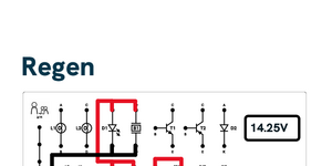
CL-1919-06-EV-schematics 14.25V Regen Hybrid 14.25V Pre-charge 14.25V HVIL 14.25V How to get ohm’s from volts 8.0V Voltage Voltage Amps Variable Meter Switch 14.5V Loss of Isolation (LOI) 14.5V Current Clamp
CL-1919-06-EV-schematics 14.25V Regen Hybrid 14.25V Pre-charge 14.25V HVIL 14.25V How to get ohm’s from volts 8.0V Voltage Voltage Amps Variable Meter Switch 14.5V Loss of Isolation (LOI) 14.5V Current Clamp

CL-1919-06_education.cdr Page 1
Operation Manual for CL-1919-06_053327 Ohm’s Law and DC Circuits Trainer 93-CL-1919-06_REVA © ConsuLab Educatech Inc, 2023. Tous droits réservés. Scan this QR code for: Operation Manual Teacher Resources https://www.consulab.com/customer-space https://www.consulab.com/customer-space CL-1919-06_053327-93 Table of contents 400-6330 Zéphirin-Paquet St. Québec QC G2C 0M3 Canada consulab.com info@consulab.com Toll-free: +1 (800) 567-0791 USA: +1 (810) 222-4525 Canada: +1 (418) 688-9067 Fax: +1 (418) 843-3444 1 © ConsuLab Educatech Inc, 2024. All rights reserved. No part of this work may be reproduced or transmitted in any form by any means, electronic, mechanical, including photocopying and recording, or by any information storage or retrieval system, without written permission from the publisher. Printed in Canada. The content of this manual is applicable to models 053327 and above. Table of contents CL-1919-06-95 Student Assignments — Table of Contents 2 CL-1919-06-96 Instructors Guide — Table of Contents 2 Trainer Layout and Familiarization 3 DMM BATTERIES AND FUSE REPLACEMENT 3 Front Panel Component Identification 4 Electrical Component Identification 5 Electrical Accessories 6 Main Fuse 6 Storage Bag 6 Jumper Leads 6 Trainer Use and Operation 7 Rating Specifications: 7 Warnings and Cautions 8 Lifting and Moving Instructions: 10 Cleaning Instructions 11 consulab.com info@consulab.com 2 CL-1919-06_053327-93 Teacher Ressources CL-1919-06-95 Student Assignments — Table of Contents CL-1919-06-96 Instructors Guide — Table of Contents CL-1919-06-95 Table of Contents 400-6330 Zéphirin-Paquet St. Québec QC G2C 0M3 Canada consulab.com info@consulab.com Toll-free: +1 (800) 567-0791 USA: +1 (810) 222-4525 Canada: +1 (418) 688-9067 Fax: +1 (418) 843-3444 2 Table of Contents Trainer Layout and Familiarization 5 Student Learning Modules 6 MODULE 1 Understanding the Digital Multimeter Setup, Use & Interpretation 8 DMM Batteries and Fuse Replacement 14 SA-1 — Measuring Resistance 15 Student Answer Sheet 18 SA-2 — Measuring DC Voltage 20 Student Answer Sheet 23 SA-3 Measuring DC Current 24 Student Answer Sheet 28 MODULE 2 Basic Electricity Theory and Understanding 30 MODULE 3 Ohm’s Law Definition and Relationships 37 SA-4 — Series Circuits 40 Student Answer Sheet 41 SA-5 — Series Circuits with One Resistance 42 Student Answer Sheet 44 SA-6 — Series Circuits with Two Resistances 45 Student Answer Sheet 48 SA-7 — Series Circuits with Two or More Resistances 49 Student Answer Sheet 51 SA-8 — Available Voltage Test 52 Student Answer Sheet 53 SA-9 — Positive Voltage Drop Testing 54 Student Answer Sheet 55 SA-10 — Ground Side Voltage Drop Testing 56 Student Answer Sheet 58 SA-11 — Parallel Circuits with Two or More Resistances 59 Student Answer Sheet 61 CL-1919-06-95 Table of Contents 400-6330 Zéphirin-Paquet St. Québec QC G2C 0M3 Canada consulab.com info@consulab.com Toll-free: +1 (800) 567-0791 USA: +1 (810) 222-4525 Canada: +1 (418) 688-9067 Fax: +1 (418) 843-3444 3 CL-1919-06-95 Table of Contents consulab.com info@consulab.com 3 SA-12 — Parallel Circuits Behavior 62 Student Answer Sheet 65 SA-13 — Circuit Behavior in Series and Parallel Circuits 67 Student Answer Sheet 69 SA-14 — Combination Series / Parallel Circuits 70 Student Answer Sheet 72 SA-15 — Series/Parallel Circuit w/Resistance in One Ground Path Branch 73 Student Answer Sheet 75 MODULE 4 Component Explanation Light Bulbs (Incadescent) 77 LED (Light Emitting Diode) 78 Buzzer 79 Diode 79 Transistors 81 Motor 83 Relay 83 Electronic Flasher 85 Potetiometer 86 Resistors 87 Fuses 87 Circuit Breakers 88 Fusible Links 89 Switches 89 Pulse Width Modulation (PWM) 91 MODULE 5 Student Experiments Student Assignment Guidelines 94 SA-16 — Light Bulb with Diode 95 Student Answer Sheet 97 SA-17 — Light Bulb Circuits 98 Student Answer Sheet 100 SA-18 — Light Bulb Circuits with Resistances 101 Student Answer Sheet 105 SA-19 — Light Bulb Circuits with Problems 106 Student Answer Sheet 109 SA-20 — Relay Circuits 110 Student Answer Sheet 112 SA-21 — Flasher Controlled Circuit 113 Student Answer Sheet 115 SA-22 — PWM Circuit with Motor 116 Student Answer Sheet 119 CL-1919-06-95 Table of Contents 400-6330 Zéphirin-Paquet St. Québec QC G2C 0M3 Canada consulab.com info@consulab.com Toll-free: +1 (800) 567-0791 USA: +1 (810) 222-4525 Canada: +1 (418) 688-9067 Fax: +1 (418) 843-3444 4 CL-1919-06-95 Table of Contents consulab.com info@consulab.com 4 SA-23 — Transistor Controlled Circuits 120 Student Answer Sheet 126 MODULE 6 Advanced Student Circuit Assignments SA-24 — Using M1 as a Generator 129 Student Answer Sheet 131 SA-25 — Alarm System — Option 1 132 Student Answer Sheet 133 SA-26 — Alarm System — Option 2 134 Student Answer Sheet 135 SA-27 — Light Bulb Dimming 136 Student Answer Sheet 137 SA-28 — Horn Circuit with Relay 138 Student Answer Sheet 139 SA-29 — Alternately Flashing Lights 140 Student Answer Sheet 141 SA-30 — Throttle Position Sensor Circuit 142 Student Answer Sheet 145 SA-31 — PWM Controlled NPN Transistor Circuit 147 Student Answer Sheet 150 SA-32 — PWM Controlled PNP Transistor Circuit 151 Student Answer Sheet 154 SA-33 — Flashing Lights Transistor Controlled Circuit 155 Student Answer Sheet 158 CL-1919-06-96 Table of Contents 400-6330 Zéphirin-Paquet St. Québec QC G2C 0M3 Canada consulab.com info@consulab.com Toll-free: +1 (800) 567-0791 USA: +1 (810) 222-4525 Canada: +1 (418) 688-9067 Fax: +1 (418) 843-3444 2 Table of Contents Trainer Layout and Familiarization 6 Student Learning Modules 7 The CL-1919-06 Learning Modules 7 CL-1919-06 Wiring Blank Template 8 MODULE 1 Understanding the Digital Multimeter Setup, Use & Interpretation 10 DMM Batteries and Fuse Replacement 15 SA-1 — Measuring Resistance 16 SA-1 — Measuring Resistance - Instructors Answer Key 17 SA-2 — Measuring DC Voltage 20 SA-2 — Measuring DC Voltage - Instructors Answer Key 21 SA-3 — Measuring DC Current 22 SA-3 — Measuring DC Current - Instructors Answer Key 23 MODULE 2 Basic Electricity Theory and Understanding 25 MODULE 3 Ohm’s Law Definition and Relationships 32 SA-4 — Series Circuit - Instructors Answer Key 35 SA-5 — Series Circuit with One Resistance - Instructors Answer Key 36 SA-5 — Series Circuit With One Resistance - Instructors Wiring Key 37 SA-6 — Series Circuits with Two Resistances - Instructors Answer Key 38 SA-6 — Series Circuits with Two Resistances - Instructors Wiring Key 39 SA-6 — Variation of Resistance Location - Instructors Wiring Key 40 SA-7 — Series Circuits with Two or More Resistances - Instructors Answer Key 41 SA-7 — Series Circuits with Two or More Resistances - Instructors Wiring Key 42 SA-8 — Available Voltage Test - Instructors Answer Key 43 SA-8 — Available Voltage Test - Instructors Wiring Key 44 SA-9 — Positive Voltage Drop Testing - Instructors Answer Key 45 SA-9 — Positive Voltage Drop Testing - Instructors Wiring Key 46 CL-1919-06-96 Table of Contents consulab.com info@consulab.com 3 SA-10 — Ground Side Voltage Drop Testing - Instructors Answer Key 47 SA-10 — Ground Side Voltage Drop Testing - Instructors Wiring Key 48 SA-11 — Parallel Circuits with Two or More Resistances - Instructors Answer Key 49 SA-11 — Parallel Circuits with Two or More Resistances - Instructors Wiring Key 50 SA-12 — Parallel Circuit Behavior- Instructors Answer Key 51 SA-12 — Parallel Circuits Behavior - Instructors Wiring Key 53 SA-13 — Circuit Behavior in Series and Parallel Circuits - Instructors Answer Key 54 SA-14 — Combination Series / Parallel Circuits - Instructors Answer Key 55 SA-14 — Combination Series / Parallel Circuits - Instructors Wiring Key 56 SA-15 — Series/Parallel Circuit with Resistance in One Ground Path Branch - Instructors Answer Key 57 SA-15 — Series/Parallel Circuit with Resistance in One Ground Path Branch - Instructors Wiring Key 58 MODULE 4 Component Explanation Component Explanation 60 MODULE 5 Student Experiments Student Assignment Guidelines 77 SA-16 — Light Bulb with Diode - Instructors Answer Key 78 SA-16 — Light Bulbs with Diode - Instructors Wiring Key 79 SA-17 — Light Bulb Circuits - Instructors Answer Key 80 SA-17 — Light Bulb Circuits - Instructors Wiring Key 81 SA-18 — Light Bulb Circuits with Resistances - Instructors Answer Key 82 SA-18 — Light Bulb Circuits with Resistances - Instructors Wiring Key 83 SA-19 — Light Bulb Circuits with Problems - Instructors Answer Key 84 SA-19 — Light Bulb Circuits with Problems - Instructors Wiring Key 85 SA-20 — Relay Circuits - Instructors Answer Key 86 SA-20B — Relay Controlled Circuit - Instructors Wiring Key 87 SA-21 — Flasher Controlled Circuit - Instructors Answer Key 88 SA-21 — Flasher Controlled Circuit - Instructors Wiring Key 89 SA-22 — PWM Circuit with Motor - Instructors Answer Key 90 SA-22 — PWM Circuit with Motor - Instructors Wiring Key 91 SA-23 — Transistor Controlled Circuits - Instructors Answer Key 92 SA-23A — NPN Transistor Circuit as a Relay Circuit - Instructors Wiring Key 94 SA-23B — PNP Transistor Circuit as a Relay Circuit - Instructors Wiring Key 95 MODULE 6 Advanced Student Circuit Assignments SA-24 — Using M1 as a Generator - Instructors Answer Key 97 SA-24 — Using M1 as a Generator - Instructors Wiring Key 98 SA-25 — Alarm System — Option 1 - Instructors Answer Key 99 SA-25 — Alarm System — Option 1 - Instructors Wiring Key 100 CL-1919-06-96 Table of Contents consulab.com info@consulab.com 4 SA-26 — Alarm System — Option 2 - Instructors Answer Key 101 SA-26 — Alarm System — Option 2 - Instructors Wiring Key 102 SA-27 — Light Bulb Dimming - Instructors Answer Key 103 SA-27 — Light Bulb Dimming - Instructors Wiring Key 104 SA-28 — Horn Circuit with Relay - Instructors Answer Key 105 SA-28 — Horn Circuit with Relay - Instructors Wiring Key 106 SA-29 — Alternately Flashing Lights - Instructors Answer Key 107 SA-29 — Alternately Flashing Lights - Instructors Wiring Key 108 SA-30 — Throttle Position Sensor Circuit - Instructors Answer Key 109 SA-30 — Throttle Position Sensor Circuit - Part One - Instructors Wiring Key 111 SA-30 — Throttle Position Sensor Circuit - Part Two - Instructors Wiring Key 112 SA-31 — PWM Controlled NPN Transistor Circuit - Instructors Answer Key 113 SA-31 — PWM NPN Transistor Controlled Circuit - Instructors Wiring Key 114 SA-32 — PWM Controlled PNP Transistor Circuit - Instructors Answer Key 115 SA-32 — PWM PNP Transistor Controlled Circuit — Part A Instructors Wiring Key 117 SA-32 — PWM PNP Transistor Controlled Circuit — Part B Instructors Wiring Key 118 SA-33 — Flashing Lights Transistor Controlled Circuit - Instructors Answers 119 SA-33A — Flashing Lights Transistor Controlled Ground Circuits - Instructors Wiring Key 120 SA-33B — Flashing Lights Transistor Controlled Positive Circuits - Instructors Wiring Key 121 SA-33 — Flashing Lights Transistor Controlled Positive & Ground Circuits - Instructors Wiring Key 122 SA-33 — Flashing Lights Transistor Controlled Positive & Ground Circuits OEM Schematic - Instructors Wiring Key 123 TESTS TEST 1 — Resistance Meter Reading 125 TEST 1 — Resistance Meter Reading - Student Answer Sheet 126 TEST 1 — Resistance Meter Reading - Instructors Answer Key 127 TEST 2 — Measuring DC Voltage 128 TEST 2 — Measuring DC Voltage - Student Answer Sheet 130 TEST 2 — Measuring DC Voltage - Instructors Answer Key 131 TEST 3 — Measuring DC Current 132 TEST 3 — Measuring DC Current - Student Answer Sheet 134 TEST 3 — Measuring DC Current - Instructors Answer Key 135 TEST 4 — Basic Meter Understanding 136 TEST 4 — Basic Meter Understanding - Student Answer Sheet 140 TEST 4 — Basic Meter Understanding - Instructors Answer Key 141 TEST 5 — Basic Electricity 142 TEST 5 — Basic Electricity - Student Answer Sheet 145 TEST 5 — Basic Electricity - Instructors Answer Key 146 TEST 6 — Ohm’s Law 147 TEST 6 — Ohm’s Law - Student Answer Sheet 149 TEST 6 — Ohm’s Law - Instructors Answer Key 150 CL-1919-06-96 Table of Contents consulab.com info@consulab.com 5 TEST 7 — Series Circuits 151 TEST 7 — Series Circuits - Student Answer Sheet 152 TEST 7 — Series Circuits - Instructors Answer Key 153 TEST 8 — Voltage Drop Testing 154 TEST 8 — Voltage Drop Testing - Student Answer Sheet 156 TEST 8 — Voltage Drop Testing - Instructors Answer Key 157 TEST 9 — Parallel Circuit Understanding 158 TEST 9 — Parallel Circuit Understanding - Student Answer Sheet 160 TEST 9 — Parallel Circuit Understanding - Instructors Answer Key 161 TEST 10 — Combination Circuit Understanding 162 TEST 10 — Combination Circuit Understanding - Student Answer Sheet 164 TEST 10 — Combination Circuit Understanding - Instructors Answer Key 165 TEST 11 — Component Explanation 166 TEST 11 — Component Explanation - Student Answer Sheet 170 TEST 11 — Component Explanation - Instructors Answer Key 171 TEST 12 — Relay Circuit Competency 172 TEST 12 — Relay Circuit Competency - Student Answer Sheet 178 TEST 12 — Relay Circuit Competency - Instructors Answer Key 179 TEST 13 — General Competency 180 TEST 13 — General Competency - Student Answer Sheet 183 TEST 13 — General Competency - Instructors Answer Key 184 TEST 14 — Final General Information and Competency 185 TEST 14 — Final General Information & Competency - Student Answer Sheet 190 TEST 14 — Final General Information & Competency - Instructors Answer Key 191 Scan this QR code for: Operation Manual Teacher Resources https://www.consulab.com/customer-space https://www.consulab.com/customer-space consulab.com info@consulab.com 3 CL-1919-06_053327-93 Trainer Layout and Familiarization Trainer Layout and Familiarization The CL-1919-06_053052 Ohm’s Law and DC Circuits Trainer contains elec- trical and electronic components mounted on a panel containing electrical connection receptacles where students complete the wiring of circuits. The trainer is designed to provide learning assistance in the understanding of basic Ohm’s Law concepts and also provides learning activities for student learning of basic circuit components and operation. A built-in 120VAC to 14VDC (4A max) power supply is internally protected and is adjustable from 2-14 VDC. The front panel contains a digital display indicating the DC voltage supply available to the trainer. Meets CSA safety requirements. The CL-1919-06 also contains a surface mounted digital multi-meter (DMM) that is powered with two AAA replaceable batteries. The ammeter fuse is located inside the meter and is easily replaced following the below procedure. NOTE: Because the trainer’s power supply output is limited to 4A, the meter’s internal 11A fuse should never need replacement. The meter is used throughout the student activities and circuit construction for electrical measurements and diagnostic training. The CL-1919-06 Ohm’s Law and DC Circuits Trainer has been certified by CSA Group a Nationally Recognized Test Laboratory, to meet the applicable standards for quality and safety in North America. This product is certified for use by persons 14 years and older only. This certification applies to both Canada and the U.S. DMM BATTERIES AND FUSE REPLACEMENT Digital Multimeters Maintenance 23 hhc07.jpg Figure 5. Replace Batteries and the Fuse BATTERY TYPE 2 x AAA, NEDA 24A, IEC LR03 FUSE TYPE 11 A, 1000 V, IR 17 kA 5 4 3 21 Reproduced with Permission, Fluke Corporation consulab.com info@consulab.com 4 CL-1919-06_053327-93 Front Panel Component Identification Front Panel Component Identification Front View 1. Trainer power cord receptacle, master ON/OFF switch and main fuse holder. 2. Positive (red) receptacles for circuit construction. These receptacles are only to be used with the trainer and not to be connected to any external devices as damage could result. 3. Negative (black) receptacles for circuit construction. These receptacles are only to be used with the trainer and not to be connected to any external devices as damage could result. 4. Digital Display for available trainer voltage (Displays the DC voltage that has been set by the voltage adjustment knob). 5. Power supply voltage adjustment knob (Adjusts the available DC voltage from 2-14 ± VDC). 6. Power supply safety reset button (Resets the internal protection cut-out. Push and hold until the O.L. light flashes, then release. The voltage display will read 0.000 when the O.L. lamp is on.). 7. Power supply “OVERLIMIT” indicator light (If a short circuit is created between the Positive & Negative sides of the trainer, the internal protection cut-out will trip and turn on the O.L. indicator light. It will remain on until the problem has been corrected and the RESET button is pushed). 8. PWM (Pulse Width Modulation) generator positive and negative receptacles. 9. PWM Adjustment knob (0-100% duty cycle). 10. Digital Multi-meter. Side View 1 3 2 47 6 5 9 8 10 consulab.com info@consulab.com 5 CL-1919-06_053327-93 Electrical Component Identification Electrical Component Identification 11. L1 – # 194 Bulb. 12. L2 – # 194 Bulb. 13. D1 – LED Bulb. 14. B1 – BUZZER. 15. T1 – NPN Transistor. 16. T2 – PNP Transistor. 17. D2 – Diode. 18. L3 – # 3157 LED Bulb. 19. M1 – DC Motor. 20. RL1 – ISO 5-pin Relay. 21. Electronic Flasher. 22. POT – 75Ω Potentiometer. 23. R1 – 100Ω Resistor. 24. R2 – 40Ω Resistor. 25. R3 – 20Ω Resistor. 26. R4 – 20Ω Resistor. 27. R5 – 2Ω Resistor. 28. F1 – Optional Circuit Fuse (ATC 2-3A). 29. SW1 – SPST Toggle Switch. 30. PB1 – N.O. Push Button Switch. Front View 11 12 13 14 15 16 17 18 19 20 21 22 23 24 25 26 27 28 29 30 consulab.com info@consulab.com 6 CL-1919-06_053327-93 Electrical Accessories Electrical Accessories Storage Bag Main Fuse Main Fuse Specifications: Model 239002P 2A, 250V, 239 Series, Slo-Blow Fuse (5 mm x 20 mm). Storage Bag Jumper Leads CL-1919-05 POWER SUPPLY FUSE SPECIFICATIONS – 239002P 2A, 250V, 239 Series, Slo-Blow Fuse (8mm x 20mm) TRAINERS MAIN FUSE LOCATION PULL TAB AWAY UNTIL FUSE HOLDER POPS OUT CLOSE UP OF MAIN FUSE HOLDER CLOSE UP OF MAIN FUSE HOLDER SPARE FUSE FUSE IN CIRCUIT CL-1919-05 POWER SUPPLY FUSE SPECIFICATIONS – 239002P 2A, 250V, 239 Series, Slo-Blow Fuse (8mm x 20mm) TRAINERS MAIN FUSE LOCATION PULL TAB AWAY UNTIL FUSE HOLDER POPS OUT CLOSE UP OF MAIN FUSE HOLDER CLOSE UP OF MAIN FUSE HOLDER SPARE FUSE FUSE IN CIRCUIT CL-1919-05 POWER SUPPLY FUSE SPECIFICATIONS – 239002P 2A, 250V, 239 Series, Slo-Blow Fuse (8mm x 20mm) TRAINERS MAIN FUSE LOCATION PULL TAB AWAY UNTIL FUSE HOLDER POPS OUT CLOSE UP OF MAIN FUSE HOLDER CLOSE UP OF MAIN FUSE HOLDER SPARE FUSE FUSE IN CIRCUIT Your product may be equipped with either of the below jumper wire styles. They are identical in specifications and performance. All CL-1919-06’s will be shipped with banana plug jumper leads including: • 10 Red Jumper Leads — 23” (60cm) long • 10 Black Jumper Leads — 23” (60cm) long consulab.com info@consulab.com 7 CL-1919-06_053327-93 Trainer Use and Operation Trainer Use and Operation The CL-1919-06-93 manual is designed to provide instructors and students with the necessary information for the prop- er and safe operation of the trainer. Note that the CL-1919-06 trainer includes student assignments (CL-1919-06-95 ) and an instructors manual (CL-1919-06-96). Be sure to read, understand and follow the instructions for each section. The CL-1919-06 is designed to be used as a “stand alone” resource to aid the instructor and students in the learning of basic electricity, Ohm’s Law, DMM meter use, basic electrical and electronic component operation, basic operational circuit construction and diagnosis and troubleshooting of circuit problems. NOTE: Before proceeding with this manual, the following tasks should have already been successfully performed and understood: 1. Familiarization with the CL-1919-06 component layout and identification (pages 5-8). 2. The CL-1919-06 should be set up on a bench/tabletop with the cover removed, the power cord plugged into the trainer and a 120VAC outlet and the master ON/OFF switch turned “on”. NOTE- The cover lid of the trainer can be placed on a table, then move the trainer on top of the cover. This po- sitions the trainer with a slight tilt providing an easier access for users. If properly completed, the digital display should be indicating the available DC voltage. For normal operation, and unless otherwise directed, the display should be adjusted to a reading of 14.0 - 14.6 ± volts. Rating Specifications: • Voltage: 100-240 VAC, single phase • Frequency: 50/60 Hz • Input Current: 2.2 A @120 VAC, 1.2 A @ 230VAC • Output current : 2-14 VDC, 4 A max. • Indoor use only • Temperature: 10 ºC – 30 ºC (50 ºF – 86 ºF) • Humidity (non-condensing): 80 % max. • Altitude : 2,000 m (6,562 ft) • Pollution Degree 2 • Overvoltage Category II Students conducting the circuit learning assignments should have completed the following Learning Modules which contain the prerequiste skills and knowledges: • Understanding basic digital multi-meter setup, use & interpretation (Student Learning Module #1). • Basic electricity (Student Learning Module #2). • Ohm’s Law (Student Learning Module #3). • Component explanation (Student Learning Module #4) • Ability to read and follow written instructions. • Ability to read and interpret basic electrical wiring schematics. consulab.com info@consulab.com 8 CL-1919-06_053327-93 Warnings and Cautions Warnings and Cautions Even though the power supply is internally protected against short-circuits and wiring errors, students should carefully read, understand and follow all activity instructions to avoid errors. NOTE- If the digital display shows “0.000” volts and the O.L. lamp is “on”, an overcurrent situation has been detected. To re-set the system, find and correct the wiring error, then push and hold the RESET button until the O.L. lamp flashes, then release. If the reset procedure was successfully completed, the display should read available voltage: 1. The 2-3A ATC blade type fuse on the trainer is for optional use by instructors and students as needed. Circuits can be connected with the fuse if desired. Remember that the trainer is internally protected to trip the over-current protection if current exceeds 4 A. 2. Access to fuse compartment and any other components inside of unit to be performed only by trained skilled per- sonnel. 3. L1 and L2 bulbs are made of glass and could break if impacted hard enough, therefore potentially creating a cutting hazard. 4. Do not connect any external device to be powered by the trainer as they may exceed the designed limits of the power supply and components. 5. Be sure to read, understand and follow each set of instructions. Be sure to ask your instructor if you have any ques- tions about any instruction or component. 6. Never “guess” about the results of a circuit. Always follow written instructions to avoid “guesswork”. 7. This product is intended for use in educational establishments by STUDENT OPERATORS at least 14 years of age and under the supervision of theRESPONSIBLE PERSON. consulab.com info@consulab.com 9 CL-1919-06_053327-93 Warnings and Cautions The following warnings and explanations apply to specific components on the trainer: 1. The ISO 5-pin relay is equipped with a current limiting resistor for the suppression of voltage spikes. It does not con- tain a protection diode, therefore the coil circuit of the relay is not polarity sensitive. Terminals 85 and 86 can both be used for positive or negativer without damage. It should be noted that most applications use terminal #85 as a coil ground circuit. 2. Specifications for the new L3 bulb: - Sylvania ZEVO 3157LED. BP2 LED light bulb, 12V – 2W - LO circuit = 35 ± milli-amps at 14.60V - HI circuit = 153 ± milli-amps at 14.60V - Non-Polarity Sensitive (Can be inserted either way) - Do not use any other 3157 bulb other than the one that came in the trainer. It is recommended that the student experiments be completed in chronological order to ensure proper understand- ing of electrical and electronic concepts. Use the blank panel templates located at the end of the Instructors Manual (CL-1919-06-96) to draw the circuits they are assigned to construct. Have students turn in the completed drawings for grading and credit. Many circuit assignments ask students to make various electrical measurements in the circuit they have constructed. An instructor answer key is provided with the correct measurement values. NOTE- Due to manufacturing tolerances of some components, it is possible to obtain readings different than those shown. Be sure to take into account this fact when evaluating student measurement readings. Most resistors and po- tentiometers have a tolerance of ±10%. The CL-1919-06 is a durable training device and weighs 10 kg (22 lbs). Precautions should be taken when lifting and mov- ing the trainer. The trainer is equipped with a convenient carrying handle. consulab.com info@consulab.com 10 CL-1919-06_053327-93 Lifting and Moving Instructions: Lifting and Moving Instructions: 1. Prior to using the carrying handle, ensure that the lid is securely attached to the trainer. Observe the hinges and ensure they are engaged properly. 2. Next check that the two attaching clasps are connected and in the closed position. 3. To move the trainer, grasp the handle and lift trainer up so that the handles face up. Once you lift the trainer, hold it close to your body. Do not twist when lifting and carrying the trainer. Point your toes in the direction you are headed and turn your entire body in that direction. 4. When placing the trainer on a table stand, the trainer vertically with the handle up and the rubber feet on the base facing you. Ensure the space is adequate and that no obstacles are present. 5. Using the handle tilt the unit towards you and lower it slowly to the horizontal position. You can now remove the lid to access the trainer by unlatching the clasps, lifting lid up until the rear hinges can be disconnected. consulab.com info@consulab.com 11 CL-1919-06_053327-93 Cleaning Instructions Cleaning Instructions 1. Prior to performing any cleaning of the trainer, ensure that it is turned off and the power cord is disconnected from the power source. 2. Use a dry lint free wipe to remove any dirt or dust from the working surface. Do not use sprays, wet wipes or chemi- cal cleaners as they could damage the surfaces and or components of the trainer. 3. Contact ConsuLab support if any damage or component malfunctions are noted. support@consulab.com mailto:support@consulab.com consulab.com info@consulab.com 12 CL-1919-06_053327-93 Notes Notes 400-6330 Zéphirin-Paquet St. Québec QC G2C 0M3 Canada © ConsuLab Educatech Inc, 2024. All rights reserved. CL-1919-06-95 Student Assignments — Table of Contents CL-1919-06-96 Instructors Guide — Table of Contents Trainer Layout and Familiarization DMM BATTERIES AND FUSE REPLACEMENT Front Panel Component Identification Electrical Component Identification Electrical Accessories Main Fuse Storage Bag Jumper Leads Trainer Use and Operation Rating Specifications: Warnings and Cautions Lifting and Moving Instructions: Cleaning Instructions
Student assignments for EM-123-4HN02_052746 Disc & drum brake trainer + faults 95-EM-123-4HN02_REVA © ConsuLab Educatech Inc, 2026. All rights reserved. 95-EM-123-4HN02 Table of contents 400-6330 Zéphirin-Paquet St. Québec QC G2C 0M3 Canada consulab.com info@consulab.com Toll-free: +1 (800) 567-0791 USA: +1 (810) 222-4525 Canada: +1 (418) 688-9067 Fax: +1 (418) 843-3444 2 © ConsuLab Educatech Inc, 2026. All rights reserved. No part of this work may be reproduced or transmitted in any form by any means, electronic, mechanical, including photocopying and recording, or by any information storage or retrieval system, without written permission from the publisher. Printed in Canada. The content of this manual is applicable to models 052746 and above. Table of contents Introduction 3 Student assignments SA1 - Student activity #1 — Master cylinder inspection service 5 SA1-A - Student activity #1-A — Master cylinder remove/replace 6 SA2 - Student activity #2 — Brake pad replacement 9 SA2-A - Student activity #2-A — Front brake disc inspection 14 SA2-B - Student activity #2-B — Front brake disc refinishing 16 SA2-C - Student activity #2-C — Front brake caliper inspection 17 SA3 - Student activity #3 — Rear brake shoe inspection and replacement 18 SA3-A - Student activity #3-A — Rear brake drum inspection and service 23 SA3-B - Student activity #3-B — Wheel cylinder inspection and service 25 SA4 - Student activity #4 — Bleeding brake service 26 consulab.com info@consulab.com 3 95-EM-123-4HN02 Introduction Introduction The EM-123-4HN02_052746 Disc & Drum Hydraulic Brake trainer is used to demonstrate the functionality of a non-ABS braking system as it operates on a real vehicle. The trainer is built with OEM components and is based on the 2010- 2006 Honda Civic platform. The trainer can be used in the classroom environment for demonstrations to students and it also has multiple built in mechanical faults. The trainer provides a safe and effective method of demonstrating the prin- ciples of braking systems used on today’s vehicles. Application 2010-2006 Honda Civic (ABS is not functional) Features • “Real” automotive components. • Individual pressure gauges at each wheel. • Components with mechanical faults. • Disc/drum four-wheel brake assemblies (NOTE- discs, drums, wheel cylinders, calipers and all friction materials are new. All other OEM components are recycled from actual vehicles). • NOTE: While there is a vacuum assist booster included on this trainer, vacuum would have to be applied from an external source to demonstrate. • Fully functional parking brake system. • Heavy Duty metal stand with casters for easy transport of trainer. • All routine brake service procedures can be performed on this trainer including component replacement, adjust- ments and hydraulic bleeding Educational advantages • This 4-wheel disc/drum braking system functions just like an actual vehicle braking system. • Trainer can be used for full mechanical service and repair operations of: - Front disc brakes - Rear drum brakes - Master Cylinder & Hydraulic system (w/ pedal) - Parking Brake system • Components with mechanical faults test students ability to precision measure and compare results to service infor- mation for a safe diagnosis. More information on the mechanical faults can be found in the instructor’s manual (EM-123-4HN02-96). • Many ASE Education Foundation (NATEF) and Red Seal tasks can be accomplished using this trainer. • Trainer can fit through a standard 30” door opening. consulab.com info@consulab.com 4 95-EM-123-4HN02 Student assignments Student assignments consulab.com info@consulab.com 5 95-EM-123-4HN02 SA1 - Student activity #1 SA1 - Student activity #1 Master cylinder inspection service 1. Look up the correct Honda brake service and safety information before proceeding. 2. Inspect and note these items : 3. Check that all parts are free of dirt and other foreign particles. Why ? 4. Do not allow dirt or foreign matter to contaminate the brake fluid. Why ? 5. Clean up work area and return tools to the proper place, hand in worksheet. Portions of materials contained herein are sourced from American Honda Motor Inc., Co. Copyright 2009 - 2013 Service Repair Solutions, Inc. Name : Group : Date : Instructor : Grade : consulab.com info@consulab.com 6 95-EM-123-4HN02 SA1-A - Student activity #1-A SA1-A - Student activity #1-A Master cylinder remove/replace (3 pages) 1. Look up the correct Honda brake service and safety information before proceeding. 2. Special tools required? 3. Be careful not to damage or bend the brake lines during removal and installation. 4. After removal, plug the ends of the hoses and the joints to prevent spilling brake fluid. Why ? 5. Remove the reservoir cap and brake fluid from the master cylinder reservoir with a syringe. 6. Disconnect the brake fluid level switch connector (A). 7. Remove the reservoir tank mounting bolt (B). consulab.com info@consulab.com 7 95-EM-123-4HN02 SA1-A - Student activity #1-A 8. Disconnect the brake lines (A) from the master cylinder (B). To prevent spills, cover the hose joints with clean rags or shop towels. 9. Remove the master cylinder mounting nuts (C) and washers (D). 10. Remove the master cylinder from the brake booster (E). Be careful not to bend or damage the brake lines when removing the master cylinder. 11. Remove the rod seal (F) from the master cylinder. NOTE: During installation, set the new rod seal onto the master cylinder with its grooved side (G) toward the master cylinder. 12. Do not try to disassemble the master cylinder assembly. 13. Honda recommends replacing the master cylinder assembly with a new part if necessary. Why ? consulab.com info@consulab.com 8 95-EM-123-4HN02 SA1-A - Student activity #1-A 14. Reinstall the master cylinder with a new rod seal in the reverse order of removal, and note these items : • Coat the inner bore lip and outer circumference of the new rod seal with the Shin-Etsu silicone grease (P/N 08798- 9013). • Make sure not to get any silicone grease on the terminal part of the connectors and switches, especially if you have silicone grease on your hands or gloves. • Check the brake pedal height and free play after installing the master cylinder, and adjust if necessary. • If the reservoir tank hose was disconnected, install the reservoir tank (A) and the reservoir tank hose (B) to the sub-reservoir (C). - NOTE : Align the ‘‘Δ ‘’ marks (D) on the reservoir tank and sub-reservoir with the paint marks (E) on the hose. Posi- tion the direction of the clamp (F). 15. Bleed the brake system (See SA-4 worksheet). 16. Spin the wheels to check for brake drag. Why? 17. Clean up work area and return tools to the proper place, hand in worksheet. Portions of materials contained herein are sourced from American Honda Motor Inc., Co. Copyright 2009 - 2013 Service Repair Solutions, Inc. Name : Group : Date : Instructor : Grade : consulab.com info@consulab.com 9 95-EM-123-4HN02 SA2 - Student activity #2 SA2 - Student activity #2 Brake pad replacement (5 pages) 1. Look up the correct Honda brake service and safety information before proceeding. 2. Special tools required ? 3. Any safety cautions to be observed ? • • • • 4. Check the thickness (A) of the inner pad (B) and the outer pad (C). Do not include the thickness of the backing plate. Brake pad thickness : Standard specifications : Service Limit specifications : 5. After inspection, are these brake pads within service limits? If not, what is recommended to do? Inner pad Outer pad consulab.com info@consulab.com 10 95-EM-123-4HN02 SA2 - Student activity #2 Replacement of pads 6. Remove some brake fluid from the master cylinder. Why ? 7. Remove the flange bolt (A), and pivot the caliper body (B) up out of the way. 8. Secure caliper up with a tie strap. Why ? 9. Check the hose and pin boots for damage and deterioration. 10. Remove the pad shims (A) and the brake pads (B). 11. Remove the pad retainers (A). consulab.com info@consulab.com 11 95-EM-123-4HN02 SA2 - Student activity #2 12. Clean the caliper bracket (B) thoroughly; remove any rust, and check for grooves and cracks. Verify that the caliper pins (C) move in and out smoothly. Clean and lube if needed. 13. Inspect the brake disc for runout, thickness, parallelism, and check for damage and cracks. *** See Student Activity SA2-A. 14. Apply a thin coat of M-77 assembly paste (P/N 08798-9010) to the retainer mating surface of the caliper bracket (indicated by the arrows). 15. Install the pad retainers. Wipe off the excess assembly paste from the retainers. Keep the assembly paste away from the brake disc and the brake pads. 16. Install the brake caliper piston compressor tool (A) on the caliper body (B). 17. Press in the piston with the brake caliper piston compressor tool so the caliper body will fit over the brake pads. 18. Make sure the piston boot is in position to prevent damaging it when pivoting the caliper body down. consulab.com info@consulab.com 12 95-EM-123-4HN02 SA2 - Student activity #2 19. NOTE : Be careful when pressing in the piston; brake fluid might overflow from the master cylinder’s reservoir. Why? 20. If brake fluid gets on any painted surface, wash it off immediately with water. 21. Remove the brake caliper piston compressor tool. 22. Apply a thin coat of M-77 assembly paste (P/N 08798-9010) to the pad side of the shims (A), the back of the brake pads (B) and the other areas indicated by the arrows. 23. Wipe off the excess assembly paste from the pad shims and the brake pads friction material. 24. Keep grease and assembly paste away from the brake disc and the brake pads. Contaminated brake disc or brake pads reduce stopping ability. 25. Install the brake pads and the pad shims correctly. 26. Why are shims needed? 27. Install the brake pad with the wear indicator (C) on the upper inside position. 28. NOTE : If you are reusing the brake pads, always reinstall the brake pads in their original positions to prevent a temporary loss of braking efficiency. consulab.com info@consulab.com 13 95-EM-123-4HN02 SA2 - Student activity #2 29. Pivot the caliper body down into position. Install the flange bolt (A), and tighten it to the specified torque. 30. Press the brake pedal several times to make sure the brakes work. 31. NOTE : Engagement may require a greater pedal stroke immediately after the brake pads have been replaced as a set. Several applications of the brake pedal will restore the normal pedal stroke. Why? 32. Add brake fluid as needed. 33. After installation, check for leaks at hose and line joints or connections, and retighten if necessary. Test-drive the vehicle, then recheck for leaks. 34. Clean up work area and return tools to the proper place, hand in worksheet. 35. Have instructor check work Name : Group : Date : Instructor : Grade : Portions of materials contained herein are sourced from American Honda Motor Inc., Co. Copyright 2009 - 2013 Service Repair Solutions, Inc. consulab.com info@consulab.com 14 95-EM-123-4HN02 SA2-A - Student activity #2-A SA2-A - Student activity #2-A Front brake disc inspection (2 pages) 1. Look up the correct Honda brake service and safety information before proceeding. Thickness and Parallelism 2. Remove the brake pads. 3. Using a micrometer (A), measure the brake disc thickness at eight points, about 45 ° apart and 10 mm (0.39 in) in from the outer edge of the brake disc. 4. Replace the brake disc if the smallest measurement is less than the maximum refinishing limit. 5. Brake disc thickness : Standard specifications : Maximum refinishing limit specifications : Brake disc parallelism* specifications : * This is the maximum allowable difference between the thickness measurements. 6. Is this disc within spec’s ? Runout 7. Inspect the brake disc to wheel surface for damage and cracks. Clean the brake disc thoroughly, and remove all rust. 8. Install suitable flat washers (A) and wheel nuts (B), and tighten the wheel nuts to the specified torque to hold the brake disc securely against the hub. 9. Set up the dial gauge (C) against the brake disc as shown, and measure the runout at 10 mm (0.39 in) from the outer edge of the brake disc. consulab.com info@consulab.com 15 95-EM-123-4HN02 SA2-A - Student activity #2-A 10. Brake disc runout specifications : Service limit : If any brake disc is beyond the service limit, what does Honda recommend as the repair ? Maximum refinishing limit : Actual runout measured : NOTE : If the brake disc is beyond the service limit for refinishing, replace it. If the brake disc is replaced with a new one, check the new disc for runout. If the new disc is out of specification, refinish the disc. 11. Clean up work area and return tools to the proper place, hand in worksheet. Name : Group : Date : Instructor : Grade : Portions of materials contained herein are sourced from American Honda Motor Inc., Co. Copyright 2009 - 2013 Service Repair Solutions, Inc. consulab.com info@consulab.com 16 95-EM-123-4HN02 SA2-B - Student activity #2-B Year and Model: VIN: Rotor Location: LF RF RR LR Rotor thickness before refinishing Rotor run-out before refinishing Rotor thickness variation (measure in 8 places): 1. 2. 3. 4. 5. 6. 7. 8. Attach to R.O. # Disc Brake Rotor Refinishing Worksheet © 2002 American Honda Motor Co., Inc. - All Rights Reserved GJA 24213 (0212) Date: Rotor Location: LF RF RR LR Rotor thickness before refinishing Rotor run-out before refinishing Rotor thickness variation (measure in 8 places): 1. 2. 3. 4. 5. 6. 7. 8. Thickest part Thinnest part Maximum variation Refinishing time overall min. Rough-cut time min. Fine-cut time min. – = Technician Signature Technician Number Rotor thickness after refinishing Rotor run-out after refinishing Thickest part Thinnest part Maximum variation Refinishing time overall min. Rough-cut time min. Fine-cut time min. – = Rotor thickness after refinishing Rotor run-out after refinishing Copyright 2009 - 2013 Service Repair Solutions, Inc. Portions of materials contained herein are sourced from American Honda Motor Inc., Co. Copyright 2009 - 2013 Service Repair Solutions, Inc. SA2-B - Student activity #2-B Front brake disc refinishing consulab.com info@consulab.com 17 95-EM-123-4HN02 SA2-C - Student activity #2-C SA2-C - Student activity #2-C Front brake caliper inspection 1. Look up the correct Honda brake service and safety information before proceeding. 2. Remove, inspect, reassemble, and install the caliper, and note any defects observed with these items : • Make sure that the caliper pins are installed correctly. Upper caliper pin and lower caliper pin are different. - If these caliper pins are installed in the wrong location, it will cause vibration, uneven or rapid brake pad wear, and possibly uneven tire wear. • To prevent dripping brake fluid, cover disconnected hose joints with clean rags or shop towels. • Before reassembling, check that all parts are free of dirt and other foreign particles. - Make sure no dirt or other foreign matter gets in the brake fluid. • Make sure no grease or oil gets on the brake discs or pads. • When reusing brake pads, always reinstall them in their original.positions to prevent loss of braking efficiency. • Do not reuse drained brake fluid. Use only new Honda DOT 3 Brake Fluid from an unopened container. - Using a non-Honda brake fluid can cause corrosion and shorten the life of the system. • Use recommended greases in the front caliper set. • After performing a visual inspection, were there any other defects noticed ? 3. After installing the caliper, check the brake hose and line for leaks, interference, and twisting. 4. Clean up work area and return tools to the proper place, hand in worksheet Portions of materials contained herein are sourced from American Honda Motor Inc., Co. Copyright 2009 - 2013 Service Repair Solutions, Inc. consulab.com info@consulab.com 18 95-EM-123-4HN02 SA3 - Student activity #3 SA3 - Student activity #3 Rear brake shoe inspection and replacement (5 pages) 1. Look up the correct Honda brake service and safety information before proceeding. CAUTION : Frequent inhalation of brake shoe dust, regardless of material composition, could be hazardous to your health. AVOID BREATHING DUST PARTICLES. Never use an air hose or brush to clean brake assemblies. Use an OSHA-approved vacuum cleaner. 2. Release the parking brake, and remove the breake drum. 3. Check the wheel cylinder for leakage (See SA3-B). consulab.com info@consulab.com 19 95-EM-123-4HN02 SA3 - Student activity #3 4. Remove the tension pins (A) by pushing the respective retainer springs (B), and turning the pin. 5. Remove the lower return spring (A), and remove the brake shoe assembly over the hub. 6. Remove the forward brake shoe (B) by removing the upper return spring (C), and disassemble the brake shoe assembly. 7. Remove the rearward brake shoe (D) by disconnecting the parking brake cable from the parking brake lever (E). consulab.com info@consulab.com 20 95-EM-123-4HN02 SA3 - Student activity #3 8. Remove the U-clip (A), the wave washer (B), and the pivot pin (C), and separate the parking brake lever (D) from the brake shoe (E). Reassembly 9. Install the parking brake lever (C) and the wave washer (D) on the pivot pin, and secure the pin with a new U-clip (E). 10. Apply Molykote 44MA grease to the sliding surface of the pivot pin (A) for the rearward brake shoe (B). 11. Connect the parking brake cable to the parking brake lever. NOTE: Pinch the U-clip securely to prevent the parking brake lever from coming out of the brake shoe 12. Apply a thin coat of Molykote 44MA grease to the connecting rod ends (A), and the sliding surfaces (B) as shown consulab.com info@consulab.com 21 95-EM-123-4HN02 SA3 - Student activity #3 13. Wipe off any excess. Keep grease away from the brake linings. 14. Install connecting rods A and B on the adjuster bolt (C). NOTE: Clean the threaded portions of connecting rod A and the sliding surface of connecting rod B, then coat them with Molykote 44MA grease. 15. Shorten connecting rod A by fully turning in the adjuster bolt. 16. Assemble the brake shoes with the upper return spring (D), with the connecting rods and the adjuster bolt onto the backing plate. 17. Reconnect the parking brake cable to the parking brake lever (E), then install the self-adjuster lever (F) and the self- adjuster spring (G) on the forward brake shoe (H). 18. Install the tension pins (A) and the retainer springs (B) by pushing in the respective spring and turning each pin. consulab.com info@consulab.com 22 95-EM-123-4HN02 SA3 - Student activity #3 19. Install the lower return spring. NOTE: Make sure the brake shoes are positioned on the brake shoe bosses on the backing plate, and the fitting on the top of the brake shoes are fitted into the wheel cylinder pistons. 20. Install the brake drum. NOTE: Before installing the brake drum, clean the mating surfaces between the hub bearing unit and the inside of the brake drum. 21. Press the brake pedal several times to make sure the brakes work and to set the self-adjusting brake. NOTE: Engagement of the brakes may require a greater pedal stroke immediately after the brake shoes have been replaced as a set. Several applications of the brake pedal will restore the normal pedal stroke. 22. Adjust the parking brake. 23. Clean up work area and return tools to the proper place, hand in worksheet. Portions of materials contained herein are sourced from American Honda Motor Inc., Co. Copyright 2009 - 2013 Service Repair Solutions, Inc. consulab.com info@consulab.com 23 95-EM-123-4HN02 SA3-A - Student activity #3-A SA3-A - Student activity #3-A Rear brake drum inspection and service (2 pages) 1. Look up the correct Honda brake service and safety information before proceeding. 2. Release the parking brake, and remove the brake drum. 3. Check the wheel cylinder (A) for leakage (See SA3-B). 4. Check the brake linings (B) for cracking, glazing, wear, and contamination. NOTE: Contaminated brake linings or drums reduce stopping ability. 5. Measure the brake lining thickness (C). Measurement does not include the metal brake shoe thickness. 6. Brake lining thickness specifications : Standard specifications : Service limit specifications : Actual measurement : 7. If any part of the brake lining thickness is less than the service limit, replace the brake shoes as a set. 8. Check the hub bearing unit (D) for smooth operation. If it requires servicing, replace the hub bearing unit. consulab.com info@consulab.com 24 95-EM-123-4HN02 SA3-A - Student activity #3-A 9. Measure the inside diameter of the brake drum with inside vernier caliper. 10. Drum inside diameter specifications : Standard specifications : Service limit specifications : Actual measurement : 11. Do the drums measure within factory specifications ? If not, what is recommended as a repair ? 12. Check the brake drum for scoring, grooves, corrosion, and cracks. 13. Install the brake drum. 14. Clean up work area and return tools to the proper place, hand in worksheet. Name : Group : Date : Instructor : Grade : Portions of materials contained herein are sourced from American Honda Motor Inc., Co. Copyright 2009 - 2013 Service Repair Solutions, Inc. consulab.com info@consulab.com 25 95-EM-123-4HN02 SA3-B - Student activity #3-B SA3-B - Student activity #3-B Wheel cylinder inspection and service 1. Look up the correct Honda brake service and safety information before proceeding. 2. Remove the brake shoes (see Student Activity SA3). 3. Disconnect the brake line (A) from the wheel cylinder (B). 4. Remove the bolts (C) and the wheel cylinder from the backing plate. NOTE: Use the special bolts on reassembly. 5. Apply Cemedine 366E sealant or equivalent between the wheel cylinder and backing plate (D), and install the wheel cylinder, then connect the brake line. 6. Install the brake shoes. Bleed the brake system. 7. Inspect and adjust the parking brake. 8. Spin the wheels to check for brake drag. 9. After installation, check for leaks at hose and line joints or connections, and retighten if necessary. 10. Clean up work area and return tools to the proper place, hand in worksheet. Portions of materials contained herein are sourced from American Honda Motor Inc., Co. Copyright 2009 - 2013 Service Repair Solutions, Inc. consulab.com info@consulab.com 26 95-EM-123-4HN02 SA4 - Student activity #4 SA4 - Student activity #4 Bleeding brake service (2 pages) 1. Look up the correct Honda brake service and safety information before proceeding. 2. Do not reuse the drained fluid. Use only new Honda DOT 3 Brake Fluid from an unopened container. Using a non- Honda brake fluid can cause corrosion and shorten the life of the system. 3. Make sure no dirt or other foreign matter gets in the brake fluid. The reservoir connected to the master cylinder must be at the MAX (upper) level mark at the start of the bleeding procedure, and checked after bleeding each wheel location. Add fluid as required. 4. Make sure the brake fluid level in the reservoir (A) is at the MAX (upper) level line (B). 5. Have someone slowly pump the brake pedal several times, then apply steady pressure. 6. Start the bleeding at the driver’s side of the front brake system. NOTE: Bleed the calipers or the wheel cylinders in the sequence shown. consulab.com info@consulab.com 27 95-EM-123-4HN02 SA4 - Student activity #4 7. Attach a length of clear drain tube (A) to the bleed screw (B), then loosen the bleed screw to allow air to escape from the system. 8. Then tighten the bleed screw securely. 9. Refill the master cylinder reservoir to the MAX (upper) level line. 10. Repeat the procedure for each brake circuit until there are no air bubbles in the fluid. 11. Clean up work area and return tools to the proper place, hand in worksheet. 400-6330 Zéphirin-Paquet St. Québec QC G2C 0M3 Canada © ConsuLab Educatech Inc, 2026. All rights reserved. Introduction Student assignments SA1 - Student activity #1 Master cylinder inspection service SA1-A - Student activity #1-A Master cylinder remove/replace (3 pages) SA2 - Student activity #2 Brake pad replacement (5 pages) SA2-A - Student activity #2-A Front brake disc inspection (2 pages) SA2-B - Student activity #2-B Front brake disc refinishing SA2-C - Student activity #2-C Front brake caliper inspection SA3 - Student activity #3 Rear brake shoe inspection and replacement (5 pages) SA3-A - Student activity #3-A Rear brake drum inspection and service (2 pages) SA3-B - Student activity #3-B Wheel cylinder inspection and service SA4 - Student activity #4 Bleeding brake service (2 pages)

CAN Bus multiplex system trainer MP-1918-1 vs MP-1918-2 Differences Rev. 2025/05 MP-1918-1 vs MP-1918-2 Differences consulab.com info@consulab.com 400-6330 Zéphirin-Paquet St. Québec QC G2C 0M3 Canada Toll-free: +1 (800) 567-0791 U.S.A.: +1 (810) 222-4525 Canada: +1 (418) 688-9067 Fax: +1 (418) 843-3444 In this document, we will outline the visual differences between the MP-1918-1 and the MP- 1918-2 models. While both versions maintain the same functionality, the results values they produce differ. It is crucial to identify which version of the product you have to ensure usage of the right manuals and interpretation of results. This guide will help you distinguish between the two models based on their visual characteristics. MP-1918-01 Panel MP-1918-1S_053040 1 2 3 4 6 5 7 8 9 1. Fault box (text format) 2. END of line resistor 1 3. Type of connector (text format) 4. Type of connector (text format) 5. Turn signal (text format) 6. Engine Brake 7. Hazard (text format) 8. Head lamps LOW (text format) 9. Head lamps PARK (text format) MP-1918-2S_053379 1 2 3 4 6 5 7 8 9 1. Instructor logo for the fault box 2. EOL 1 (usage of the End of line abbreviation) 3. Usage of the Truck logo to indicate the truck indus- try DLC 4. Usage of the Car logo to indicate the automotive industry DLC 5. Turn signal symbol 6. Engine brake for Truck / Regen brake for Electric car 7. Hazard symbol 8. Generic Head lamps LOW symbol 9. Generic park lamps symbol MP-1918-1 vs MP-1918-2 Differences consulab.com info@consulab.com 400-6330 Zéphirin-Paquet St. Québec QC G2C 0M3 Canada Toll-free: +1 (800) 567-0791 U.S.A.: +1 (810) 222-4525 Canada: +1 (418) 688-9067 Fax: +1 (418) 843-3444 MP-1918-02 Panel MP-1918-1S_053040 1 2 3 4 5 6 1. Engine Control Module 2. Engine Coolant Temperature 3. Idle Variation (text format) 4. Pedal Position (text format) 5. CAN Bus Junction block 6. END of line resistor 2 MP-1918-2S_053379 1 2 3 4 5 6 1. Powertrain Control Module (apply to truck and car) 2. ECT (usage of the Engine Coolant Temperature abbreviation) 3. Turtle symbol (apply to truck (PTO) and car (low gear)) 4. Gradation symbol 5. No identification of CAN Bus Junction block 6. EOL 2 (usage of the End of line abbreviation)

CAN Bus multiplex system trainer MP-1918-1 vs MP-1918-2 Differences Rev. 2025/05 MP-1918-1 vs MP-1918-2 Differences consulab.com info@consulab.com 400-6330 Zéphirin-Paquet St. Québec QC G2C 0M3 Canada Toll-free: +1 (800) 567-0791 U.S.A.: +1 (810) 222-4525 Canada: +1 (418) 688-9067 Fax: +1 (418) 843-3444 In this document, we will outline the visual differences between the MP-1918-1 and the MP- 1918-2 models. While both versions maintain the same functionality, the results values they produce differ. It is crucial to identify which version of the product you have to ensure usage of the right manuals and interpretation of results. This guide will help you distinguish between the two models based on their visual characteristics. MP-1918-01 Panel MP-1918-1S_053040 1 2 3 4 6 5 7 8 9 1. Fault box (text format) 2. END of line resistor 1 3. Type of connector (text format) 4. Type of connector (text format) 5. Turn signal (text format) 6. Engine Brake 7. Hazard (text format) 8. Head lamps LOW (text format) 9. Head lamps PARK (text format) MP-1918-2S_053379 1 2 3 4 6 5 7 8 9 1. Instructor logo for the fault box 2. EOL 1 (usage of the End of line abbreviation) 3. Usage of the Truck logo to indicate the truck indus- try DLC 4. Usage of the Car logo to indicate the automotive industry DLC 5. Turn signal symbol 6. Engine brake for Truck / Regen brake for Electric car 7. Hazard symbol 8. Generic Head lamps LOW symbol 9. Generic park lamps symbol MP-1918-1 vs MP-1918-2 Differences consulab.com info@consulab.com 400-6330 Zéphirin-Paquet St. Québec QC G2C 0M3 Canada Toll-free: +1 (800) 567-0791 U.S.A.: +1 (810) 222-4525 Canada: +1 (418) 688-9067 Fax: +1 (418) 843-3444 MP-1918-02 Panel MP-1918-1S_053040 1 2 3 4 5 6 1. Engine Control Module 2. Engine Coolant Temperature 3. Idle Variation (text format) 4. Pedal Position (text format) 5. CAN Bus Junction block 6. END of line resistor 2 MP-1918-2S_053379 1 2 3 4 5 6 1. Powertrain Control Module (apply to truck and car) 2. ECT (usage of the Engine Coolant Temperature abbreviation) 3. Turtle symbol (apply to truck (PTO) and car (low gear)) 4. Gradation symbol 5. No identification of CAN Bus Junction block 6. EOL 2 (usage of the End of line abbreviation)
Unpacking and Setup Instructions for 1918 Series (CL-HV-MP) Automotive Lighting System Trainers 1918 Series_Unpacking and Setup_V2024-2 © ConsuLab Educatech Inc, 2024. All rights reserved. 1918 Series (CL-HV-MP) Unpacking and Setup Instructions consulab.com info@consulab.com 2 Unpacking and Setup Instructions Thank you for purchasing one of the 1918 Series lighting trainers. We hope that you enjoy this product and find it very useful for the training of students in the design, operation, diagnosis, and repair of automotive lighting circuits. Please carefully follow the below instructions for unpacking and setup of this trainer. After initial unpacking and set-up, refer to the following instructions for trainer use. 1. UNPACKING • Please carefully examine the shipping pallet and all boxes for signs of shipment damage. If any damage is noticed, please take pictures, and send to support@consulab.com to report any abnormal conditions noticed. • Carefully remove any shrink wrap, tie-downs or other shipping materials attaching the trainers frame and boxes to the pallet. • Set the trainers frame on the floor. Notice that all four casters are the swivel design and can be locked at desired location. mailto:support@consulab.com 1918 Series (CL-HV-MP) Unpacking and Setup Instructions consulab.com info@consulab.com 3 2. SETUP • ConsuLab identifies these panels as Moduponents™. The three Moduponents™ are identified with embossed yellow letters located on the upper left corner of each panel. • The correct Moduponent™ identifications are: - CL-1918-01A, HV-1918-01A or MP-1918-01A for the front vehicle lighting panel - CL-1918-02A, HV-1918-02A or MP-1918-02A for the instrument panel - CL-1918-03A, HV-1918-03A or MP-1918-03A for the rear vehicle lighting panel. • Insert the three panels into the frame in the following order: CL/HV/MP-1918-03A (bottom) CL/HV/MP-1918-02A (middle) CL/HV/MP-1918-01A (top) IMPORTANT – Notice that the middle and top Moduponents™ of 1918 trainers have a multi-connector electrical plug that must be connected after the Moduponents™ are installed in the frame. Access the two connecters from behind the Moduponents™ Notice the polarity positioning method and connect the two plugs together making sure that they are fully engaged. MODUPONENT™ ID NUMBER SERIAL NUMBER DIGITS HV-1918 CL-1918 MP-1918 top middle bottom top middle bottom 1918 Series (CL-HV-MP) Unpacking and Setup Instructions consulab.com info@consulab.com 4 • Notice that there is a storage drawer on each side of the trainer’s frame. The drawer is lockable and the keys for the drawer, the ignition switch and the trainers fault box are be attached to one of the black plastic Moduponent™ clips. Locate the keys and open the storage drawer. There are three sets of two keys each for the following: - Two (2) ignition switch keys (A) - Two (2) fault box keys (B) - Two (2) storage drawer keys (A). • If you purchased a “double-sided” trainer, each drawer will have supplies for that side of the trainer. If you purchased a single side trainer, one drawer will be empty. The contents of the drawer are as follows: CL-1918 HV-1918 MP-1918 • 6 Long red test leads - 19 A (1 m - 39.4 in) • 8 Long black test leads - 19 A (1 m - 39.4 in) • 50 Short red test leads - 19 A (50 cm - 19.7 in) • 25 Short black test leads - 19 A (50 cm - 19.7 in) • 1 Trainer power cord • 1 Test lead holder & small hardware package • 6 Long red test leads - 19 A (1 m - 39.4 in) • 8 Long black test leads - 19 A (1 m - 39.4 in) • 50 Short red test leads - 19 A (50 cm - 19.7 in) • 25 Short black test leads - 19 A (50 cm - 19.7 in) • 1 Trainer power cord • 1 Test lead holder & small hardware package • 1 Long red test leads - 19 A (1 m - 39.4 in) • 21 Long black test leads - 19 A (1 m - 39.4 in) • 25 Short red test leads - 19 A (75 cm - 29.5 in) • 8 Short green test leads - 19 A (50 cm - 19.7 in) • 8 Short yellow test leads - 19 A (50 cm - 19.7 in) • 1 Trainer power cord • 1 Test lead holder & small hardware package • Attach the two blue metal test lead holder to one side of the trainer frame at the top as shown. Use screws and washers. • Distribute the test leads into the lead holders. B A 1918 Series (CL-HV-MP) Unpacking and Setup Instructions consulab.com info@consulab.com 5 • Once the power supply’s power cord is plugged into a 120V receptacle, the power supply is turned on/off with a red rocket switch located on the right-side of the power supply. The power supply is internally protected from short-circuits. The power supply is equipped with an ammeter and voltmeter. Meters will display system current and voltage as trainer is used. There will be a separate power supply for each side of a double-sided trainer (if equipped) WARNING: The power supply should NEVER be used as a battery charger due to potential serious component damage and the voiding of the warranty. The power supply is specifically designed ONLY to supply a DC power source for our trainers. Connecting the Power Supply to the Moduponent™ Panels Before the CL/HV/MP-1918-02A (middle panel) is mounted to the frame, notice that there is a black two wire terminal block mounted inside on one side of the frame. A black and a red wire is attached to the terminal block using friction tabs which are also connected to the power supply. A flat tip screwdriver of the proper size is used to push in on each friction tab to either insert or remove a wire. Locate the red and black wires coming from the back side of the middle panel and properly connect them to the terminal block. When the middle panel’s red and black wires are properly connected to the power supply terminal block and when the power supply is turned on, the RED power indicator light on the middle panel should illuminate. NOTE : Confirm that the trainer’s power cord is plugged into a receptacle. NOTE : It is normal for the power indicator light to stay on for a few seconds after power supply is switched off. • The student assignments and instructors manuals are available on our website as download- able PDF files. • You have now unpacked and set up the CL-1918-3 trainer. Please make note of any damage, missing parts or other conditions and contact call Support @ 1-800-567-0791 for customer service or support@consulab.com. CL-1918-4S_053304-93 Trainer Use and Familiarization consulab.com info@consulab.com 4 Release tabs PUSH IN Push to release and attach When the middle panel’s red and black wires are properly connected to the power supply terminal block and when the power supply is turned on, the RED power indicator light on the middle panel should illuminate. NOTE : Confirm that the trainer’s power cord is plugged into a receptacle. NOTE : It is normal for the power indicator light to stay on for a few seconds after power supply is switched off. Circuit Construction Wires: There are black and red jumper wires of different lengths used for students constructing various circuits on the trainer. The ends of the jumper wires are equipped with terminal plugs that allow them to be “stacked” on top of each other which allows more than one wire to be connected to the same receptacle. When stacking jumper wires, try to avoid using more than 3-4 at one connection point. Fuse Section : The trainer is equipped with a fuse section consisting of eight fuses of different amperages. The top three fuses are pow- ered from a common bus connected to the power supply. The other five fuses must be powered with jumper wires. (see fuse box details) ALWAYS connect all circuits through a fuse. FUSE PANEL INFORMATION MUST BE FED FROM B+ FEED EX.: IGN SWITCH F1 - F3 HOT AT ALL TIMES F4 - F8 CKT’S TO BE SWITCHED WITH B+ GND BAT 1ACOM COM 1A GND SIG BAT MAIN PWR 25A PWR RLY 5A CL-1918-02A_053317 REVB BRAKE SWITCH BACK-UP SWITCH HORN BREAKER 0.5A HORN BUTTON HAZARD FLASHER TURN SIGNAL FLASHER GND SIG BAT 10A OFF LEFT INDICATOR HIGH BEAM INDICATOR RIGHT INDICATOR MULTIFUNCTION SWITCH SIG RIGHTLEFTHEADPARKFLASHHIGHLOW DIMMER LIGHTS TURN IGNITION SWITCH CANCEL LEVER LEFT RIGHTGND SIG HAZARD SWITCH RELAY 3 RELAY 4 87A 30 8685 87A87 30 87 8685 BAT ACC IGN START F1 F2 F3 F4 F5 F6 F7 F8 10A 10A 10A 10A 20A 15A 5A F9 MAIN POWER PROTECTION FUSE 25A F10 POWER RELAY PROTECTION mailto:support@consulab.com

ConsuKit Student-Built Brushless DC Motor EV-100_053374 Rev. 2025/06 EV-100_053374 ConsuKit Student-Built Brushless DC Motor consulab.com info@consulab.com 400-6330 Zéphirin-Paquet St. Québec QC G2C 0M3 Canada Toll-free: +1 (800) 567-0791 U.S.A.: +1 (810) 222-4525 Canada: +1 (418) 688-9067 Fax: +1 (418) 843-3444 EDUCATIONAL ADVANTAGES For Students For Teachers The EV-100 ConsuKit Student-Built Brushless DC Motor is a powerful hands- on teaching tool for STEM, engineering, and trades programs. Students build a real 3-phase motor or generator from scratch, exploring coil design, mag- net placement, and wiring. Safe for classroom use (12V DC) and capable of up to 6000 RPM, it delivers real-world results and sparks curiosity in electric vehicles, renewable energy, and automation. Modular, easy to assemble, and backed by step-by-step guides and student worksheets, the EV-100 bridges theory and practice in an unforgettable learning experience. The EV-100 ConsuKit Student-Built Brushless DC Motor provides significant educational bene- fits for both students and teachers. • Offers a hands-on learning experience that reinforces electrical and mechanical concepts for real-world application. • Allows students to build and test their own motor or generator, developing practical skills in wiring, assembly, and troubleshooting. • Integrates knowledge from multiple disciplines such as physics, electrical engineering, automation, and renewable energy, making it ideal for STEM and trades programs. - In STEM and general science classes, it enables hands-on application of abstract con- cepts like electromagnetism, induction, and energy conversion. - Supports physics courses by reinforcing principles such as torque, voltage generation, and rotational motion. - Provides real-world training in motor construction, wiring, and circuit behavior for elec- trical and electronics technology programs. -Highly relevant for engineering and mechatronics courses focused on motor control, power systems, and system integration. - Trades and apprenticeship programs — such as those for electricians, industrial me- chanics, and automotive technicians — gain practical skills and safe experimentation opportunities. -Demonstrates energy generation and storage concepts applicable to wind and solar systems, supporting green energy and environmental studies. -Connects directly to electric vehicle propulsion systems and regenerative braking for automotive technology training. -Adaptable design and rich instructional support bridge theory and practice across multiple disciplines and skill levels. • Promotes critical thinking, problem-solving, and creativity through experimentation with coil configurations, magnet placement, and wiring setups. • Serves as a flexible and adaptable tool that fits into various curriculums from junior high to post-secondary levels. • Includes ready-to-use instructional materials like step-by-step guides and student work- sheets, simplifying lesson planning and delivery. • Operates on a safe 12V DC range, encouraging safe, inquiry-based exploration in the classroom. • Connects classroom learning directly to emerging technologies in electric vehicles and clean energy. EV-100_053374 ConsuKit Student-Built Brushless DC Motor consulab.com info@consulab.com 400-6330 Zéphirin-Paquet St. Québec QC G2C 0M3 Canada Toll-free: +1 (800) 567-0791 U.S.A.: +1 (810) 222-4525 Canada: +1 (418) 688-9067 Fax: +1 (418) 843-3444 Scan this QR code for more about this product FEATURES TECHNICAL INFORMATIONS • Students can experiment with coil configurations, magnet placement, and wiring, enhanc- ing hands-on learning. • The transparent housing offers clear visibility of internal components, reinforcing visual understanding. • Packaged in a sturdy storage cardboard box, ensuring secure and organized transporta- tion of all components between classrooms or labs. Dimensions Storage Box : 9 x 9 x 4 inch ( 22.86 x 22.86 x 10.16 cm) Product once built : 3.53 x 6.59 x 3.76 inch (8.96 x 16.74 x 9.55 cm) Weight : Storage Box : 3 lb (1.36 kg) Product once built : 1 lb (0.45 kg)

Answer Keys and Theory for EM-1100_053254 Planetary Gear Set Trainer Teacher Only 91-EM-1100_REVA © ConsuLab Educatech Inc, 2025. All rights reserved. 91-EM-1100 Table of contents 400-6330 Zéphirin-Paquet St. Québec QC G2C 0M3 Canada consulab.com info@consulab.com Toll-free: +1 (800) 567-0791 USA: +1 (810) 222-4525 Canada: +1 (418) 688-9067 Fax: +1 (418) 843-3444 2 © ConsuLab Educatech Inc, 2025. All rights reserved. No part of this work may be reproduced or transmitted in any form by any means, electronic, mechanical, including photocopying and recording, or by any information storage or retrieval system, without written permission from the publisher. Made in Canada. The content of this manual is applicable to models 053254 and above. Table of contents Theory Basic operation 4 Main Components 5 Student Assignments Answers SA-1 — Component Identification - Answers 7 SA-2 — Power Transfer - Answers 8 Test Results and Analysis 10 SA-3 — Calculation of Gear Ratios 11 SA-3 — Calculation of Gear Ratios — Answers 13 Test Results and Analysis 14 SA-4 — Compound Gear Ratios 15 SA-4 — Compound Gear Ratios — Answers 16 Test Results and Analysis 16 SA-5 — Understanding and Calculating Ratios of an Allison 1000 Transmission (Advanced) 17 SA-5 — Understanding and Calculating Ratios of an Allison 1000 Transmission (Advanced) — Answers 18 Test Results and Analysis 19 SA-6 — Understanding SIMPSON (2th speed) compound planetary gear ratios of an Allison 1000 Series transmission (Advanced) 20 SA-6 — Understanding SIMPSON (2th speed) compound planetary gear ratios of an Allison 1000 Series transmission (Advanced) — Answers 21 Quiz and Additional Questions on Planatery Gear Trains 22 Part 1 : Multiple choice questions — Answers 22 Part 2 : Additional Questions — Answers 22 Part 3 : Planetary Gears and Mathematics — Answers 23 91-EM-1100 Theory consulab.com info@consulab.com 3 Theory 91-EM-1100 Titre de la section consulab.com info@consulab.com 4 Basic operation : • A planetary gear train consists of three main components, each of which can serve a different function depending on how the gear set is used: - Input member: the component that is driven and supplies torque - Reaction member: the component that is held stationary or controlled - Output member: the component that delivers the resulting motion and torque • When one member of a planetary gear train is driven, the other two members are forced to rotate. By selecting which component is driven, which is held, and which is used as the output, the planetary gear train can produce multiple gear ratios, including forward gears and reverse. • To transmit torque through a planetary gear train: - One member applies a rotating torque (input), - A second member resists motion by being held stationary or controlled (reaction), - The third member rotates as a result and delivers the output torque. • Each of the three members can alternate between the roles of input, reaction, and output. The different combina- tions of these roles determine: - The number of available gear ratios - Whether the output rotates in the same or opposite direction (reverse gear) • In some applications, the reaction member is not completely stationary but is allowed to rotate in either direction under control. This creates a continuously variable gear ratio and is commonly used in hybrid vehicle transmissions. • Torque transmission within a planetary gear train occurs in several stages, beginning with the driven input member and ending with the rotation of the output member. The terms drive and driven simply describe the relationship between components transmitting motion. • For clarity, in a planetary gear train: - The drive member is referred to as the input member - The held member is referred to as the reaction member - The driven member is referred to as the output member consulab.com info@consulab.com 5 91-EM-1100 Theory — Main Components Main Components : • Sun gear : In yellow, at center. • Planet pinions : In green, mounted on the planet carrier. • Ring gear : In black, external gear around the inner gears. 91-EM-1100 Student Assignments consulab.com info@consulab.com 6 Student Assignments Answers 91-EM-1100 Component Identification consulab.com info@consulab.com 7 SA-1 — Component Identification - Answers Perform all tests following the procedure below as instructed. Identifying and learning the names of planetary gear train components is crucial for understanding and effectively dis- cussing the system’s operation and advancing in student assignments. Objective : Identify and label the components of a simple planetary gear set. Material Required : ConsuLab EM-1100 Planetary gear set trainer. Procedure : 1. Inspect the planetary gear set trainer. 2. Identify the components on the EM-1100 with the correct number : Sun gear : 2 Planet pinions : 3 Ring gear : 1 Planet carrier : 4 3. Count the number of teeth for each of the following gears : Sun gear : 12 Planet pinions : 12 Ring gear : 36 1 2 3 4 91-EM-1100 SA-2 — Power Transfer consulab.com info@consulab.com 8 SA-2 — Power Transfer - Answers Perform all tests following the procedure below as instructed. This assignment helps students understand the connections between components and learn the fundamental functions of a planetary gear set. Objective : Identify the component movements according to the 6 different blocking scenarios offered by the EM-1100 trainer. Material Required : ConsuLab EM-1100 Planetary gear set trainer. To begin with, you need to understand two concepts : input value and power output value. The input value (motor) is at the gear driven by you and the output value is at the second gear that will be moving. To generate power transfer, it is necessary to hold one of the components. When none of the components are held, there is no power transfer. There- fore, rotating a gear will not produce any output value. This scenario represents the neutral position. Procedure : In the following steps, you will experiment with the 6 power transfer scenarios available with the EM-1100. Scenario #1 : 1. Install the locking pin at the sun gear (A). 2. Hold the planet carrier handle and rotate three times. 3. Which gear represents the power output value ? Ring gear 4. Regarding the power output gear, do we have a scenario improving torque or speed ? Speed 5. How many turns do you get at the power output gear after three complete rotations of the planet carrier ? 4 turns 6. So the input/output ratio is 3 for 4 or 1 for 1 1/3 A B C A : Sun Gear Locking B : Planet Carrier Locking C : Ring Gear Locking 91-EM-1100 SA-2 — Power Transfer consulab.com info@consulab.com 9 Scenario #2 : 1. Install the locking pin at the ring gear (C). 2. Hold the planet carrier handle and rotate 180°. 3. Which gear represents the power output value ? Sun gear 4. Regarding the power output gear, do we have a scenario improving torque or speed ? Speed 5. How many turns do we get at the output gear after a complete 180° rotation of the planet carrier ? 4 turns 6. So the input/output ratio is 4 for 1 Scenario #3 : 1. Install the locking pin at the sun gear (A). 2. Hold the ring gear handle and rotate four times. 3. Which gear represents the power output value ? Planet carrier 4. Regarding the power output gear, do we have a scenario improving torque or speed ? Torque 5. How many turns do we get at the output gear after four rotations of the ring gear ? 3 turns 6. So the input/output ratio is 4 for 3 or 1 for 3/4 Scenario #4 : 1. Install the locking pin at the ring gear (C). 2. Hold the sun gear handle and rotate four times. 3. Which gear represents the power output value ? Planet carrier 4. Regarding the power output gear, do we have a scenario improving torque or speed ? Torque 5. How many turns do we get at the output gear after four rotations of the sun gear ? 1 turn 6. So the input/output ratio is 4 for 1 Scenario #5 : 1. Install the locking pin at the planet carrier (B). 2. Hold the sun gear handle and rotate three times. 3. Which gear represents the power output value ? Ring gear 4. Regarding the power output gear, do we have a scenario improving torque or speed ? Torque 5. How many turns do we get at the output gear after three rotations of the sun gear ? 1 reverse turn or -1 6. So the input/output ratio is 3 for -1 91-EM-1100 SA-2 — Power Transfer consulab.com info@consulab.com 10 Scenario #6 : 1. Install the locking pin at the planet carrier (B). 2. Hold the ring gear handle and rotate 180°. 3. Which gear represents the power output value ? Sun gear 4. Regarding the power output gear, do we have a scenario improving torque or speed ? Speed 5. How many turns do we get at the output gear as a result of a 180° rotation of the ring gear ? 3 reverse turns or -3 6. So the input/output ratio is 1 for -3 Test Results and Analysis Power transfer scenarios on an epicyclic gear train can improve torque, speed or reverse the output value of the mecha- nism, depending on which gears are held in rotation or locked by the pin on the EM-1100 trainer rear side. Increased torque scenarios • Two increased torque scenarios are used during the assignment, meaning that output speed is reduced, but torque is higher. • These scenarios are ideal for applications requiring high torque at low speeds (Ex. : Low speed transmission clutch, heavy vehicle starters, winches and industrial robots); • You can note effort reduction on the input motor. This opens up possibilities at the level of system strength. Increased speed scenarios : • Two increased speed scenarios are used during the assignment, meaning that output speed is increased, but torque is reduced • These scenarios are ideal for applications requiring high speed at low torque. (Ex. : High speed transmission clutch, fast rotating tools, industrial fans, or propulsion systems that require quick response.) • You can note effort increase on the input motor, which allows the system to operate faster when the issue is speed rather than torque. Reverse operating scenarios : • Two reverse operating scenarios are used during the assignment, which allows reverse as the output direction while improving torque level or power output speed. • These scenarios are ideal for applications requiring variable reverse gear, such as farm tractors, winches or mobile robots. • The planetary gear set design allows this reversal to be achieved without adding complex mechanisms, while ensur- ing a smooth and robust transmission. The reverse operating scenario modulates the input motor driving force, and improves the versatility of the system in reverse rotation. 91-EM-1100 SA-3 — Calculation of Gear Ratios consulab.com info@consulab.com 11 SA-3 — Calculation of Gear Ratios Perform all tests following the procedure below as instructed. The importance of the correlation between the planetary gear train component movements and mathematics It is essential to understand that complex mechanical systems, such as planetary gears, cannot be fully understood without a solid foundation in mathematics. The movements of sun gear, planet carrier and ring gear are not random : They obey precise laws, expressed through algebraic formulas Mathematics acts here as a universal language, allowing to model, predict and optimize the behavior of the system. Without this understanding, the analysis remains superficial, even erroneous. Just take the example of the Willis for- mula, which allows the angular velocities of different components in the epicyclic gear train to be linked. This algebraic formula is essential to correctly analyze the transmission ratios in these systems The origin of the formula comes from Robert Willis, a 19th century British engineer and mechanic who contributed to the formalization of the laws of gear kinematics. He introduced this formula in his work on machine theory, notably in his book called Principles of Mechanism that was published in 1841. Willis was one of the first scientists to propose a systematic method to analyze relative speeds in complex mechanisms such as epicyclic gear trains, using the principle of motion superposition. Mastering the mathematical formulas associated with mechanical products is not a luxury, but a must. It not only en- ables better system design and diagnosis, but also efficient communication between engineers, researchers and techni- cians across language barriers. The objective of the following assignments is not to make you a proficient mathematician, but rather to allow you to handle simplified formulas already established. This will help you better understand the logic and structure underlying the operation of the system. 91-EM-1100 SA-3 — Calculation of Gear Ratios consulab.com info@consulab.com 12 Objective : Understand and calculate gear ratios for a simple planetary gear train. Material Required : Willis formulas, calculator and ConsuLab EM-1100 planetary gear set trainer. Procedure : Use the formulas required to calculate the gear ratios between the sun gear, planet carrier and ring gear. The Willis formula is a fundamental expression in the mechanics of gear systems, particularly in the analysis of epicyclic or planetary gears. It is used to link the rotational speeds of various components in the system. Each power transfer scenario can result in an algebraic formula. It is important to make the link. First, you must be able to interpret the algebraic formulas and the names of variables. To facilitate understanding, the original formulas have been adapted to allow the student to identify the variables and follow the process clearly and precisely. Simplified variables • Number : ( ) • Sun Gear : ( ) • Ring Gear or Crown : ( ) • Planet Carrier : ( ) If the planet carrier is stationary, the relationship is reversed and negative. In formulas, it is essential to understand the following algebraic abbreviations : • : Number of teeth in the ring gear • : Number of teeth in the sun gear • : Number of teeth in the planet carrier • The negative sign ( ) indicates that the output is rotating in the opposite direction to the input. Table of scenarios Scenario Stationary Component Input Output Adapted Willis Formula 1 Ring Gear Sun Gear Planet Carrier Ratio = 2 Ring Gear Planet Carrier Sun Gear Ratio = 3 Sun Gear Ring Gear Planet Carrier Ratio = 4 Sun Gear Planet Carrier Ring Gear Ratio = 5 Planet Carrier Ring Gear Sun Gear Ratio = 6 Planet Carrier Sun Gear Ring Gear Ratio = 91-EM-1100 SA-3 — Calculation of Gear Ratios consulab.com info@consulab.com 13 There are six different gear ratios that you can calculate, adding a direct drive (1 :1 ratio) and a neutral position (no output). For an enhanced experience, manipulate your ConsuLab EM-1100 planetary gear set to properly understand formulas used during scenarios. Refer to the “example” on the next page to correctly answer the questions in all steps. 1. Scenario #1 (example) : Use the suggested formula in the scenario table to calculate the ratio of the system using the following combination : Stationary ring gear, sun gear at input, planet carrier at output and explain the effect obtained by this scenario. A. Formula : Ratio = = 4:00 B. Ratio : 4:00/1 (Input/Output) C. Effect : Reduced speed and increased torque D. Direction of rotation : Same way SA-3 — Calculation of Gear Ratios — Answers 2. Scenario #2 : Use the suggested formula in the scenario table to calculate the ratio of the system using the following combination : Stationary ring gear, sun gear at input, planet carrier at output and explain the effect obtained by this scenario. A. Formula : Ratio = = 0.25 B. Ratio : 0.25 for 1 or can also be expressed as 4 to 1 C. Effect : Increased speed, reduced torque D. Direction of rotation : Same direction 3. Scenario #3 : Use the suggested formula in the scenario table to calculate the ratio of the system using the following combination : Stationary sun gear, ring gear at input, planet carrier at output and explain the effect obtained by this scenario. A. Formula : Ratio = = 0.75 B. Ratio : 1 for 0.75 or can also be expressed as 1.25 to 1 C. Effect : Reduced speed, increased torque D. Direction of rotation : Same direction 4. Scenario #4 : Use the suggested formula in the scenario table to calculate the ratio of the system using the following combination : Stationary planet carrier, sun gear at input, ring gear at output and explain the effect obtained by this scenario. A. Formula : Ratio = = 0.33 B. Ratio : 1 for -0.33 or can also be expressed as 1.33 to 1 C. Effect : Reduced speed, increased torque D. Direction of rotation : Reverse direction 91-EM-1100 SA-3 — Calculation of Gear Ratios consulab.com info@consulab.com 14 5. Scenario #5 : Use the suggested formula in the scenario table to calculate the ratio of the system using the following combination : Stationary sun gear, planet carrier at input, ring gear at output and explain the effect obtained by this scenario. A. Formula : Ratio = = 1.333 B. Ratio : 1 for 1.333 or 1 for 1 1/3 C. Effect : Increased speed, reduced torque D. Direction of rotation : Same direction 6. Scenario #6 : Use the suggested formula in the scenario table to calculate the ratio of the system using the following combination : Stationary planet carrier, ring gear at input, sun gear at output nd explain the effect obtained by this scenario. A. Formula : Ratio = = -3 B. Ratio : 1 for -3 can also be expressed as 0.33 to 1 C. Effect : Increased speed, reduced torque. D. Direction of rotation : Reverse direction Test Results and Analysis The six scenarios demonstrate the great flexibility of planetary systems in power transmission. Depending on the combi- nation of stationary, input and output components, you can achieve many varied effects on speed, torque and direction of rotation. For example, when the ring gear is stationary and the sun gear is at input (scenario #1), the system produces a ratio of 4 to 1, which reduces speed while increasing torque, with rotation in the same direction. Conversely, in scenario #2, where the ring gear is still stationary but the planet carrier is at input, the ratio is 0.25 to 1, which increases the speed but reduces the torque, while maintaining the same direction of rotation. Some scenarios, such as scenarios #4 and #6, introduce a change in direction of rotation (negative ratio), which is crucial for some mechanical applications. Overall, these tests show that each configuration directly influences the mechanical performance of the system, allowing the transmission to be operated accordingly to the specific needs of a mechanism, whether to increase force, speed or reverse movement. It is important to master planetary gear systems, as it develops the understanding of the mechanisms used in many modern machines. This learning allows you to analyze, diagnose and optimize technical systems, the essential tasks of a student to succeed in the mechanical, engineering and maintenance trades. 91-EM-1100 SA-4 — Compound Gear Ratios consulab.com info@consulab.com 15 SA-4 — Compound Gear Ratios Perform all tests following the procedure below as instructed. In this activity, we explore a transmission system based on multiple compound planetary gearsets, a configuration commonly used in speed reduction mechanisms. We find this type of assembly, where the elements chain together to transmit movement in a fluid and controlled way, especially in Allison automatic transmissions, renowned for their per- formance in heavy vehicles. To calculate the gear ratio of a system with compound epicyclic (or planetary) gears, we use the Willis formula for each stage and then multiply the individual ratios together. P1 P2 P3 This cutaway Allison transmission from ConsuLab demonstrates technology with three compound planetary gears. The change of its 6 speeds is possible thanks to the clutch of the friction discs connected to various elements such as the sun gear, the planet carrier and the ring gear of each of the three planetary trains. Objective : Understand and calculate gear ratios for a double and then triple compound planetary set by using the mathematical principles of Willis formulas. Material required : Willis formulas, calculator and ConsuLab EM-1100 planetary gear set. 91-EM-1100 SA-4 — Compound Gear Ratios consulab.com info@consulab.com 16 SA-4 — Compound Gear Ratios — Answers 1. Use the formulas provided in the SA-3 table to calculate the gear ratios between the sun gear, planet carrier and ring gear. Multiply the formulas to calculate the scenario involving the second identical planetary set coupled to the first as follows : A. First planetary gear set (P1) : • Sun gear : Input • Ring gear : Stationary • Planet carrier : Output • Formula : Ratio = = 4 • Ratio : 4 for 1 B. Second planetary gear set (P2) : • Sun gear : Input (driven by the first gear planet carrier) • Ring gear : Stationary • Planet carrier : Output • Formulas : P1 Planetary Gear Set P2 Planetary Gear Set (Ratio = = 4) X (Ratio = = 4) = 16 • Ratio : 16 for 1 • Effect : Reduced speed, increased torque • Direction of Rotation : Same direction 2. Use Willis formulas provided in the SA-3 table to calculate the gear ratios between the sun gear, the planet carrier and the ring gear. Multiply the formulas to calculate the scenario involving the third identical planetary set coupled to the first as follows : • Sun gear : Input (driven by the second gear planet carrier) • Ring gear : Stationary • Planet carrier : Output • Formulas : P1 Planetary P2 Planetary P3 Planetary (Ratio = = 4) X (Ratio = = 4) X (Ratio = = -4) = -48 • Ratio : 48 for 1 • Effect : Reduced speed, increased torque • Direction of Rotation : Reverse direction Test Results and Analysis The system studied in this student assignment consists of three identical planetary gears, each with a sun gear with 12 teeth and a ring gear with 36 teeth. In the first two stages, the ring gear is locked and power is transmitted from the sun gear to the planet carrier, reducing the speed by a factor of 4 at each stage. In the third stage, the planet carrier is locked and power enters through the sun and exits through the ring gear, which reverses the direction of rotation and applies a ratio of −3. This assignment deals with only one of the six configurations offered by the Allison Transmission. If you have successfully assimilated the information transmitted after these tests, you will now master very well the notions of epicyclic systems. 91-EM-1100 SA-5 — Understanding and Calculating Ratios of an Allison 1000 Transmission (Advanced) consulab.com info@consulab.com 17 SA-5 — Understanding and Calculating Ratios of an Allison 1000 Transmission (Advanced) Perform all tests following the procedure below as instructed. Similarly to SA-4, we will study a transmission system based on three compound planetary gearsets and explore the configuration of the speed reduction mechanism used by the Allison transmission. This time you will use actual transmis- sion data to compare the manufacturer’s specifications with the results you have obtained from the suggested scenario to determine which transmission gear is engaged. Objective : Understand and calculate gear ratios for a planetary assembly used on the Allison transmission, using the mathematical principles of the Willis formula and the exact specifications of the system. Material Required : Willis formulas and calculator. Explanations : The Allison 1000 transmission is an automatic transmission equipped with several clutches (C1 to C5), electrically controlled by solenoids. It uses three epicyclic gear trains (P1, P2 and P3) to manage the gear ratios. • C1 and C2 are rotary clutches that transmit engine torque to various components of the planetary gears. C1 con- nects the input shaft to the common sun gear of planetary gears P2 and P3 • C3, C4 and C5 are stationary clutches that block certain components, such as ring gears and planet carriers, to change the gear ratio. Input Shaft Output Shaft P1 P2 P3 C3 C4 C5 C1 C2 91-EM-1100 SA-5 — Understanding and Calculating Ratios of an Allison 1000 Transmission (Advanced) consulab.com info@consulab.com 18 Each clutch combination changes how power flows through the planetary gears. This allows different gear ratios to be obtained. The clutch combinations on the Allison transmission are as follows : Speed Ratios C1 C2 C3 C4 C5 1st 3.09:1 2nd 1.81:1 3rd 1.41:1 4th 1.00:1 5th 0.71:1 (Overdrive) 6th 0.61:1 Reverse 4.49:1 Neutral Park Clutch applied Clutch not applied Each gear on the Allison 1000 transmission has a unique and precise number of teeth that provide specific ratios : • P1 (Ring gear : 113 teeth / Sun gear : 61 teeth) → Ratio ≈ 2.85 • P2 (Ring gear : 113 teeth / Sun gear : 57 teeth) → Ratio ≈ 2.98 • P3 (Ring gear : 113 teeth / Sun gear : 54 teeth) → Ratio ≈ 3.09 Procedure : Answer the following questions by referring to the previous information and table. SA-5 — Understanding and Calculating Ratios of an Allison 1000 Transmission (Advanced) — Answers 1. Clutch activation : Which clutches are engaged when first gear is activated ? In first speed, clutches C1 and C5 are engaged. 2. On which gear(s) is power transferred when first gear is activated ? In first gear, the power transfer is at planetary P3 only. 3. Describe the scenario, including the clutches used and the planetary components of the power transfer (input shaft to transmission output shaft) when first gear is engaged. Refer to the illustration on the previous page ? The sun gear of P2 and P3 rotates, engaged on the input shaft by C1, the crown of P3 is fixed and held on the outer wall by C5. Therefore, the planet carrier of P3 rotates and transmits the torque to the wheels via the output shaft of the transmission. 91-EM-1100 SA-5 — Understanding and Calculating Ratios of an Allison 1000 Transmission (Advanced) consulab.com info@consulab.com 19 4. Use the required formula to calculate the ratio (velocity #1) of the system using the previous combination and ex- plain the effect achieved by this scenario : - Formula : Ratio = - Ratio : 3.094 - Effect : Reduced speed, increased torque - Direction of rotation : Same direction Test Results and Analysis The Allison transmission first gear reduction ratio indicates that the engine rotates 3.094 times for each revolution of the output shaft. This gives a high torque for starting, ideal for heavy loads. Transmission Speed Ratio Speed Clutch applied 1st 3.09 :1 C1 and C5 2nd 1.81 :1 C1 and C4 3rd 1.41 :1 C1 and C3 4th 1.00 :1 C1 and C2 5th 0.71 :1 (Overdrive) C2 and C3 6th 0.61 :1 C2 and C4 Reverse 4.49 :1 C3 and C5 Neutral — C5 only Park — C5 only 91-EM-1100 Titre de la section consulab.com info@consulab.com 20 91-EM-1100 SA-6 — Understanding SIMPSON (2th speed) compound planetary gear ratios of an Allison 1000 Series transmission (Advanced) SA-6 — Understanding SIMPSON (2th speed) compound planetary gear ratios of an Allison 1000 Series transmission (Advanced) The operation of the Simpson system is certainly the most difficult scenario. In general, a planetary works this way : • An input member. • Another is held fixed and is called the reaction member. • The third becomes the output member. A complex feature of planetary gear technology is when two cascading planetary gears transmit power to each other on two different elements, for example, when the Allison transmission second gear is engaged, the normally fixed reaction member is now rotating, the reaction member becomes the second input member which can be difficult to assimilate as everything rotates. The Simpson epicyclic gear train is a gear system consisting of two planetary gear trains sharing a common sun and a link with the planet carrier and ring gear of the clutch, which allows great compactness and high mechanical efficiency. In this configuration, the two sun gears are mechanically linked or driven by the same shaft, this configuration causes a particular phenomenon at the level of the sun gear P3, which is driven by two sources of movement simultaneou sly : On the one hand by the sun shared with the second gear P2, and on the other hand by the mechanical link with the planet carrier P2 and the ring P3. This double contribution of power to P3 makes it a strate- gic driving element, capable of combining the effects of rotation of the two trains. This phenomenon opens the way to greater flexibility in the trans- mission ratios, since it makes it possible to modulate the speed and the torque transmitted as a function of the fixed or engaged elements (ring gear, planet carrier, sun). Thus, the Simpson train can generate multiple gear ratios with fewer compo- nents, while optimizing the continuity and fluidity of the transmission. Thanks to this architecture, the Simpson train provides multiple forward gears and reverse gear with a reduced number of components, making it a robust and economical solution for transmission systems. Input Shaft Output Shaft P1 P2 P3 C3 C4 C5 C1 C2 consulab.com info@consulab.com 21 91-EM-1100 SA-6 — Understanding SIMPSON (2th speed) compound planetary gear ratios of an Allison 1000 Series transmission (Advanced) SA-6 — Understanding SIMPSON (2th speed) compound planetary gear ratios of an Allison 1000 Series transmission (Advanced) — Answers 1. What is the difference between a one-member input configuration (classical system) and a two-member input config- uration (Simpson system) ? A. One-member input : Classic transmission where only one component receives the power, the others are stationary or output B. Two-member input : Advanced transmission (everything rotates) where two components receive power and the other is output. This allows for more complex combinations and increased flexibility in speed and torque ratios. 2. What is the main advantage of a two-input member Simpson system for modern automatic transmissions ? The main advantage is the ability to achieve multiple forward gears and one reverse gear with a reduced number of components. This design allows for a robust and economical solution, while ensuring great compactness and high mechanical efficiency in modern automatic transmissions. 3. In the Simpson two-input member configuration of the Allison transmission, which two components can be driven simultaneously ? What is the effect on planetary P3 ? The two input members are the shared sun gear (common to both planetaries P2 and P3) and the planet carrier of the second sun gear. This dual input drives sun gear P3, both via the shared sun gear and via the mechanical con- nection to planet carrier P2 and ring gear P3. In terms of effect, P3 receives power from two sources, allowing the speed and torque transmitted to be modulated depending on which elements are fixed or engaged. consulab.com info@consulab.com 22 91-EM-1100 Quiz and Additional Questions on Planatery Gear Trains Quiz and Additional Questions on Planatery Gear Trains Part 1 : Multiple choice questions — Answers Circle the correct answer. 1. What is the main role of the EM-1100 trainer ? A. Introduce the student to basic ratio calculations B. Introduce the student to the principles of planetary gears C. Introduce the student to the principles of manual transmissions D. Introduce the student to astronomy 2. What are the three main elements of a planetary gear train ? A. Sun gear, planetary gears (planet carrier), ring gear B. Helical gear, sun gear, ring gear C. Spur gear, shaft, sprocket D. Ring gear, shaft, sun gear 3. Which component must be stationary to obtain the neutral position in the planetary system ? A. None B. Sun gear C. Planet carrier D. Crown 4. What is the main advantage of planetary gears in modern automatic transmissions ? A. Their low cost B. Their robustness and compactness C. Their low efficiency D. Their complexity Part 2 : Additional Questions — Answers 5. Name two industrial applications where planetary gears are used. - Transmissions and differentials for heavy wheeled equipment - #Hydraulic motors for excavator turrets (Also included : electric starters, transmissions for racing cars, heavy trucks, drills, grinders, and children’s toys). consulab.com info@consulab.com 23 91-EM-1100 Quiz and Additional Questions on Planatery Gear Trains 6. Explain the difference between a torque-enhancing scenario and a speed-enhancing scenario in a planetary gear train. Give examples of application. Torque : A torque-enhancing scenario reduces output speed but increases transmitted torque, which is ideal for applications requiring high torque at low speeds. Examples of application : Heavy vehicle starters, winches, industrial robots Speed : A speed-enhancing scenario increases output speed but reduces torque, making it suitable for applications requiring high speed at low torque Examples of application : Rotary tools (drill grinders), some industrial fans and some propulsion systems 7. What is the main difference between straight teeth and helical teeth on a planetary gear ? Straight teeth are parallel to the axis of rotation, while helical teeth are inclined and spiral around the axis. This difference affects how the gears engage and transmit power. 8. What are the advantages of helical teeth over straight teeth in a gear system ? Helical teeth provide a more gradual and quieter contact, improving smoothness of operation and reducing noise. They also allow for smoother power transmission. Part 3 : Planetary Gears and Mathematics — Answers 9. Willis formulas are effective for finding the gear ratio. Identify the formula to use for each of the following scenarios : A. Scenario : Stationary ring gear, sun gear at the input, planet carrier at the output Formula : Ratio = B. Scenario : Stationary ring gear, planet carrier at the input, sun gear at the output Formula : Ratio = C. Scenario : Stationary planet carrier, sun gear at the input, ring gear at the output Formula : Ratio = D. Scenario : Stationary sun gear, ring gear at the input, planet carrier at the output Formula : Ratio = 10. When we have a system consisting of two planetary gear sets in cascade, how is the total gear ratio calculated ? Willis formula should be used for each stage, then you multiply the individual ratios between them. Give an example of formula : 11. Why is it important to master the mathematical formulas associated with planetary gears in mechanics ? Because they allow us to model, predict, and optimize system behavior, better design and diagnose systems, and effective communication between professionals. Mathematics acts as a universal language, enabling us to model, predict, and optimize system behavior. Without this understanding, analysis remains superficial. consulab.com info@consulab.com 24 91-EM-1100 Notes Notes 400-6330 Zéphirin-Paquet St. Québec QC G2C 0M3 Canada © ConsuLab Educatech Inc, 2025. All rights reserved. Theory Basic operation : Main Components : Student Assignments Answers SA-1 — Component Identification - Answers SA-2 — Power Transfer - Answers Test Results and Analysis SA-3 — Calculation of Gear Ratios SA-3 — Calculation of Gear Ratios — Answers Test Results and Analysis SA-4 — Overlapped Gear Ratios SA-4 — Overlapped Gear Ratios — Answers Test Results and Analysis SA-5 — Understanding and Calculating Ratios of an Allison 1000 Transmission (Advanced) SA-5 — Understanding and Calculating Ratios of an Allison 1000 Transmission (Advanced) — Answers Test Results and Analysis SA-6 — Understanding SIMPSON (2th speed) compound planetary gear ratios of an Allison 1000 Series transmission (Advanced) SA-6 — Understanding SIMPSON (2th speed) compound planetary gear ratios of an Allison 1000 Series transmission (Advanced) — Answers Quiz and Additional Questions on Planatery Gear Trains Part 1 : Multiple choice questions — Answers Part 2 : Additional Questions — Answers Part 3 : Planetary Gears and Mathematics — Answers

Instructor Manual for EM-1100_053254 Planetary gear set trainer 96-EM-1100_REVA © ConsuLab Educatech Inc, 2025. All rights reserved. Teacher Only Scan this QR code for: Operation Manual Teacher Resources https://www.consulab.com/customer-space 96-EM-1100 Table of contents 400-6330 Zéphirin-Paquet St. Québec QC G2C 0M3 Canada consulab.com info@consulab.com Toll-free: +1 (800) 567-0791 USA: +1 (810) 222-4525 Canada: +1 (418) 688-9067 Fax: +1 (418) 843-3444 3 © ConsuLab Educatech Inc, 2025. All rights reserved. No part of this work may be reproduced or transmitted in any form by any means, electronic, mechanical, including photocopying and recording, or by any information storage or retrieval system, without written permission from the publisher. Printed in Canada. The content of this manual is applicable to models 053254 and above. Table of contents Trainer Use and Familiarization 4 Introduction 5 Main composants 6 Educational functions 7 Pedagogical approach 8 Task correlation 9 Additional information 10 Technical Terms Glossary 11 96-EM-1100 Trainer use and familiarisation consulab.com info@consulab.com 4 Trainer Use and Familiarization This manual is designed to provide instructors with all the fault descriptions and schematics. This manual is for the teacher eyes only as it reveals some answers and fault location. Be sure to read, understand and follow all content of the Operation Manual and the Instructors Guide before using the product, those will provide a safe working environment for students and instructors. Those two manuals are also available in PDF format on our website. The product comes with two more manuals, Student Assignments manual and Answer keys and theory manual, which are available in PDF format on our website. The Student Assignments manual contain a theory section with student as- signments activitites and tests. The Answer keys and theory manual contain the same theory section, plus some note for the instructor, and the answer to the student assignments and tests. • Operation Manual • Instructors Guide • Student Assignments • Answers Keys and Theory • Operation Manual • Instructors Guide Scan this QR code for: Operation Manual Teacher Resources https://www.consulab.com/customer-space https://www.consulab.com/customer-space 96-EM-1100 Introduction consulab.com info@consulab.com 5 Introduction The EM-1100 is a mechanical training tool designed to introduce students to the fundamentals of a planetary gear sys- tem. It consists of three main components: The yellow sun gear (in the center), the green planetary gears (mounted on a planet carrier) and the black ring gear (external gear). By assigning each of these components a specific role, either as input, output or stationary element, the instructor can demonstrate different mechanical configurations such as reduction, overdrive, reverse gear or direct drive. Thanks to its fully manual design, the EM-1100 trainer allows students to manipulate parts, observe the effects of each configuration, and better understand the principles of movement transmission and speed variation. This tool promotes an interactive, visual and concrete educational approach, ideal for stimulating analysis and discussion in class. 96-EM-1100 Main components consulab.com info@consulab.com 6 Main composants • Sun Gear : In yellow, located in the center. • Planet Pinions : In green, mounted on a planet carrier. • Ring Gear : In black, external gear surrounding the sun gear and the planet carrier. • Locking pin: Blocks either the sun gear, the planet pinions or the ring gear according to the scenario chosen during the student assignments. 96-EM-1100 Educational functions consulab.com info@consulab.com 7 Educational functions The EM-1100 trainer demonstrates: • Two (2) forward reductions • Two (2) forward overdrive • Two (2) reverse modes • Direct drive (1:1) • Neutral position Each configuration is obtained by modifying the input, output, and stationary component roles (reaction member), which illustrates: • The variation of the transmission ratio • Reversal of the direction of rotation • The blocking or release effect of components 96-EM-1100 Pedagogical approach consulab.com info@consulab.com 8 Pedagogical approach To simplify the complex functioning of a transmission, the best pedagogical approach is to start with the basics and progress gradually. It is essential to introduce concepts step by step, increasing the level of explanations as students assimilate the fundamentals. When an open transmission is observed, the huge number of components can make under- standing difficult or even discouraging for a learner. The ConsuLab planetary gear set student assignments help to bypass this obstacle by isolating key elements of the planetary system and presenting them clearly and sequentially. By assimilating one by one the stages of movement transmission and power transfer, the student develops a solid and structured understanding Once the fundamental principles are well mastered by students, the instructor can then introduce more complex sys- tems, such as the integration of overlapped planetary gears combined with clutches. This logical progression allows students to visualize how the combination of these elements can modulate the power or speed of a vehicle depending on how the clutch configurations are activated. The EM-1100 trainer thus becomes an essential stepping stone toward understanding modern automatic transmis- sions. We recommend that the instructor guides his students through the identification of components (sun gear, planet pinions, planet carrier and ring gear) and encourages them to experiment with different configurations so as to observe the effects on speed and direction of rotation. Trainer can be used in a class demonstrations or exploratory workshops, depending on the level of the group. Feel free to incorporate analytical questions or practical challenges to stimulate reflection and autonomy. 96-EM-1100 Task correlation consulab.com info@consulab.com 9 Task correlation Industrial applications and advantages of planetary gear trains Epicyclic gears, generally called planetary gear trains, are present in a multitude of mechanical configurations and play a central role in several industrial sectors. We can find them in children’s toys, drills, grinders and all kinds of rotating tools. They are found in transmissions, differentials for heavy equipment vehicles, axle drive units (final drives), mechan- ical excavator turret hydraulic motors and electric starters. They are also used for racing car transmissions and heavy trucks, especially those in extreme forestry fleet. In industrial applications, Allison branded transmissions stand out for their performance, particularly thanks to the efficient integration of this technology. Planetary gear trains offer several major advantages, starting with space optimi- zation, because all shafts can be aligned on the same axis. Firstly, this allows for compact power transmission, unlike traditional transmissions that require larger overlapped gears. Secondly, their robustness is remarkable: It is possible to increase the load capacity by adding additional planetary gears. No interruption of power flow is necessary. When changing gear, the epicyclic system does not require coupling or synchronization between the gears. These systems are also known for their easy maintenance, as they require little intervention to remain in good working order Planetary gear trains can have several configurations in terms of the type of gears used: The angle and type of teeth (straight or helical) optimize compactness, load supported and smooth operation. For example, helical teeth provide more gradual and quiet contact than straight teeth, but generate additional axial forces. Thus, the tooth diversity types makes it possible to adapt the gears to mechanical, spatial and acoustic constraints according to the needs of the manu- facturers. Finally, they are highly appreciated when designing power transmission systems due to the simplicity of ratio calcula- tions and the flexible configurations, thus facilitating the planning and optimization of mechanical performance. 96-EM-1100 Additional Information consulab.com info@consulab.com 10 Additional information • The devices that hold or drive certain parts of the planetary assembly are mostly hydraulic disc clutches (clutch pack). • On the EM-1100, six gear ratios are possible (see table below): # SUN GEAR PLANET CARRIER RING GEAR SPEED TORQUE DIRECTION 1. Input (motor) Output (driven) Stationary Max. Reduction Increase Same as Input 2. Output (driven) Input (motor) Stationary Max. Increase Reduction Same as Input 3. Stationary Output (driven) Input (motor) Min. Reduction Increase Same as Input 4. Stationary Input (motor) Output (driven) Min. Increase Reduction Same as Input 5. Input (driven) Stationary Output (driven) Reduction Increase Input Reverse 6. Output (driven) Stationary Input (motor) Increase Reduction Input Reverse • If two planetary gear train elements are locked together, the output ratio is 1:1, in the same direction as the input (direct drive). • If no element is stationary, there is no reaction, which corresponds to a neutral position. • The planetary gears can be combined to form a compound assembly. A common example is the SIMPSON set, which consists of two planetary gear trains sharing a common sun gear. With a Simpson package, three forward gears and one reverse gear are possible. consulab.com info@consulab.com 11 96-EM-1100 Technical Terms Glossary Technical Terms Glossary Sun gear Toothed gear located at the center of the planetary system, typically shown in yellow in ConsuLab equipment. It is one of the three main components of the planetary gearset. Planet pinions Small gears (in green) that rotate around the sun gear and are mounted on the planet carrier. Ring gear Large external gear (in black) that surrounds the planet pinions. Planet carrier Support on which the planet pinions are mounted, allowing them to rotate around the sun gear. Input member The component of the planetary gearset to which motion or engine torque is applied. Output member The component of the planetary gearset that transmits motion or torque out of the system. Reaction member A component held stationary or immobilized to enable torque transmission and create different gear ratios. Locking (Immobilization) The action of holding a component (sun gear, ring gear, or planet carrier) stationary to achieve a specific operating mode or ratio. Gear ratio The ratio between the rotational speed of the input element and that of the output element. It determines the increase or decrease in speed and torque. Torque Rotational force transmitted by the gear system. Direction of rotation The orientation of the output motion relative to the input (same direction or opposite direction). consulab.com info@consulab.com 12 96-EM-1100 Technical Terms Glossary Neutral position Configuration in which no component is immobilized, preventing motion from being transmitted to the output. Direct drive (1:1) Configuration in which two components are locked together, resulting in a transmission ratio of 1:1 (same input and out- put speed). Willis formula Mathematical formula used to calculate speed ratios in a planetary gearset based on the components used as input, output, or reaction members. Compound planetary gearset A system that includes multiple planetary gearsets combined to produce more complex transmission ratios (e.g., Simp- son system). Hydraulic clutch pack A device that locks or releases certain components of the planetary gearset, commonly used in automatic transmis- sions. Allison 1000 transmission An example of an automatic transmission using multiple planetary gearsets and clutches to obtain different gear ratios. Simpson system A type of compound planetary gearset made of two assemblies sharing a common sun gear, allowing multiple forward speeds and one reverse gear. Spur teeth / Helical teeth Types of gear teeth: spur teeth are parallel to the axis, while helical teeth are angled, providing quieter and smoother operation. consulab.com info@consulab.com 13 96-EM-1100 Notes Notes consulab.com info@consulab.com 14 96-EM-1100 Notes Notes 400-6330 Zéphirin-Paquet St. Québec QC G2C 0M3 Canada © ConsuLab Educatech Inc, 2025. All rights reserved. Trainer Use and Familiarization Introduction Main composants Educational functions Pedagogical approach Task correlation Additional information Technical Terms Glossary