


93-EV-360_operation-manual_REVA.pdf
Operation Manual for EV-360_053325 ADAS (Advanced Driver Assist Systems) Trainer 93-EV-360_REVA © ConsuLab Educatech Inc, 2025. Tous droits réservés. Scan this QR code for: Operation Manual Teacher Resources https://www.consulab.com/customer-space Student Assignments Step by Step Animations Available on YouTube https://www.consulab.com/customer-space 93-EV-360 Table of contents 6330 Zéphirin-Paquet Street, Suite 400 Québec, QC G2C 0M3 Canada consulab.com info@consulab.com Toll-free: +1 (800) 567-0791 USA: +1 (810) 222-4525 Canada: +1 (418) 688-9067 Fax: +1 (418) 843-3444 3 Table of Contents Teacher Resources 4 95-EV-360 Student Assignments — Table of Contents 4 91-EV-360 Answer Key — Table of Contents 4 96-EV-360 Instructors Manual — Table of Contents 4 Purpose and Function 5 The EV-360 and Heavy-Duty Vehicles 6 Unpacking 7 Infrastructure Requirements 7 Pre-operation Checks 8 Support Contact Information 8 Setup 9 Trainer Component Identification 10 Display Screens 11 Explanation of Sensor Screens 13 ADAS Sensor Theory 17 Safety Instructions 17 Basic Operation 18 © ConsuLab Educatech Inc, 2025. All rights reserved. No part of this work may be reproduced or transmitted in any form by any means, electronic, mechanical, including photocopying and recording, or by any information storage or retrieval system, without written permission from the publisher. Printed in Canada. The content of this manual is applicable to models 035325 and above. consulab.com info@consulab.com 4 93-EV-360 Teacher Resources Scan this QR code for: Operation Manual Teacher Resources https://www.consulab.com/customer-space Teacher Resources We have included the table of contents from three other manuals in this operation manual. This serves as a reference to make you aware of all the documentation that comes with the product. 95-EV-360 Student Assignments — Table of Contents 91-EV-360 Answer Key — Table of Contents 96-EV-360 Instructors Manual — Table of Contents EV-360_053325-95 Table of contents 400-6330 Zéphirin-Paquet St. Québec, QC G2C 0M3 Canada consulab.com info@consulab.com Toll-free: +1 (800) 567-0791 USA: +1 (810) 222-4525 Canada: +1 (418) 688-9067 Fax: +1 (418) 843-3444 2 © ConsuLab Educatech Inc, 2025. All rights reserved. No part of this work may be reproduced or transmitted in any form by any means, electronic, mechanical, including photocopying and recording, or by any information storage or retrieval system, without written permission from the publisher. Printed in Canada. The content of this manual is applicable to models 053325 and above. Table of Contents Purpose and Function 3 ADAS Sensor Theory 4 Basic Operation 5 Educational Advantages 8 Main Features 8 Explanatory Animation 8 SA-1 Six Levels of Autonomous Driving 9 SA-2 ADAS Acronyms 10 SA-3 ADAS Components 11 SA-4 ADAS Theory Exploration 12 SA-5 ADAS Sensor Fusion 15 SA-6 ADAS Object Identification Exploration 16 SA-7 ADAS Sensor Accuracy 17 SA-8 Understanding Steering Angle Calibration 18 EV-360 Set-up for Student Assignments 19 SA-9 Understanding BSD Calibration 20 SA-10 Understanding Front Facing RADAR Calibration 25 SA-11 Understanding LiDAR Calibration 28 SA-12 Understanding Front Camera Calibration 31 SA-13 Understanding Ultrasonic Proximity Sensor Calibration 34 SA-14 Understanding Rear Camera Calibration 36 SA-15 ADAS Pre-Calibration 39 SA-16 ADAS Vehicle Specific 40 EV-360_053325-95 Table of contents 400-6330 Zéphirin-Paquet St. Québec, QC G2C 0M3 Canada consulab.com info@consulab.com Toll-free: +1 (800) 567-0791 USA: +1 (810) 222-4525 Canada: +1 (418) 688-9067 Fax: +1 (418) 843-3444 2 © ConsuLab Educatech Inc, 2025. All rights reserved. No part of this work may be reproduced or transmitted in any form by any means, electronic, mechanical, including photocopying and recording, or by any information storage or retrieval system, without written permission from the publisher. Printed in Canada. The content of this manual is applicable to models 053325 and above. Table of Contents Purpose and Function 3 ADAS Sensor Theory 4 Basic Operation 5 Educational Advantages 8 Main Features 8 Explanatory Animation 8 SA-1 Six Levels of Autonomous Driving 9 SA-2 ADAS Acronyms 10 SA-3 ADAS Components 11 SA-4 ADAS Theory Exploration 12 SA-5 ADAS Sensor Fusion 15 SA-6 ADAS Object Identification Exploration 16 SA-7 ADAS Sensor Accuracy 17 SA-8 Understanding Steering Angle Calibration 18 EV-360 Set-up for Student Assignments 19 SA-9 Understanding BSD Calibration 20 SA-10 Understanding Front Facing RADAR Calibration 25 SA-11 Understanding LiDAR Calibration 28 SA-12 Understanding Front Camera Calibration 31 SA-13 Understanding Ultrasonic Proximity Sensor Calibration 34 SA-14 Understanding Rear Camera Calibration 36 SA-15 ADAS Pre-Calibration 39 SA-16 ADAS Vehicle Specific 40 EV-360_053325-91 Table of contents 400-6330 Zéphirin-Paquet St. Québec, QC G2C 0M3 Canada consulab.com info@consulab.com Toll-free: +1 (800) 567-0791 USA: +1 (810) 222-4525 Canada: +1 (418) 688-9067 Fax: +1 (418) 843-3444 2 © ConsuLab Educatech Inc, 2025. All rights reserved. No part of this work may be reproduced or transmitted in any form by any means, electronic, mechanical, including photocopying and recording, or by any information storage or retrieval system, without written permission from the publisher. Printed in Canada. The content of this manual is applicable to models 053325 and above. Table of Contents Purpose and Function 3 ADAS Sensor Theory 4 Basic Operation 5 Educational Advantages 8 Main Features 8 Explanatory Animation 8 SA-1 Six Levels of Autonomous Driving - Answers 9 SA-2 ADAS Acronyms − Answers 10 SA-3 ADAS Components − Answers 11 SA-4 ADAS Theory Exploration - Answers 12 SA-5 ADAS Sensor Fusion - Answers 15 SA-6 ADAS Object Identification Exploration - Answers 16 SA-7 ADAS Sensor Accuracy - Answers 17 SA-8 Understanding Steering Angle Calibration - Answers 18 EV-360 Set-up for Student Assignments - Answers 19 SA-9 Understanding BSD Calibration - Answers 20 SA-10 Understanding Front Facing RADAR Calibration - Answers 25 SA-11 Understanding LiDAR Calibration - Answers 28 SA-12 Understanding Front Camera Calibration - Answers 31 SA-13 Understanding Ultrasonic Proximity Sensor Calibration - Answers 34 SA-14 Understanding Rear Camera Calibration - Answers 36 SA-15 ADAS Pre-Calibration - Answers 39 SA-16 ADAS Vehicle Specific - Answers 40 EV-360_053325-96 Table of contents 400-6330 Zéphirin-Paquet St. Québec, QC G2C 0M3 Canada consulab.com info@consulab.com Toll-free: +1 (800) 567-0791 USA: +1 (810) 222-4525 Canada: +1 (418) 688-9067 Fax: +1 (418) 843-3444 3 © ConsuLab Educatech Inc, 2025. All rights reserved. No part of this work may be reproduced or transmitted in any form by any means, electronic, mechanical, including photocopying and recording, or by any information storage or retrieval system, without written permission from the publisher. Printed in Canada. The content of this manual is applicable to models 053325 and above. Table of contents Trainer Use and Familiarization 4 Purpose and Function 5 Educational Advantages 6 Main Features 6 Explanatory Animation 6 The EV-360 and Heavy-Duty Vehicles 7 EV-360_053325-91 Table of contents 400-6330 Zéphirin-Paquet St. Québec, QC G2C 0M3 Canada consulab.com info@consulab.com Toll-free: +1 (800) 567-0791 USA: +1 (810) 222-4525 Canada: +1 (418) 688-9067 Fax: +1 (418) 843-3444 2 © ConsuLab Educatech Inc, 2025. All rights reserved. No part of this work may be reproduced or transmitted in any form by any means, electronic, mechanical, including photocopying and recording, or by any information storage or retrieval system, without written permission from the publisher. Printed in Canada. The content of this manual is applicable to models 053325 and above. Table of Contents Purpose and Function 3 ADAS Sensor Theory 4 Basic Operation 5 Educational Advantages 8 Main Features 8 Explanatory Animation 8 SA-1 Six Levels of Autonomous Driving - Answers 9 SA-2 ADAS Acronyms − Answers 10 SA-3 ADAS Components − Answers 11 SA-4 ADAS Theory Exploration - Answers 12 SA-5 ADAS Sensor Fusion - Answers 15 SA-6 ADAS Object Identification Exploration - Answers 16 SA-7 ADAS Sensor Accuracy - Answers 17 SA-8 Understanding Steering Angle Calibration - Answers 18 EV-360 Set-up for Student Assignments - Answers 19 SA-9 Understanding BSD Calibration - Answers 20 SA-10 Understanding Front Facing RADAR Calibration - Answers 25 SA-11 Understanding LiDAR Calibration - Answers 28 SA-12 Understanding Front Camera Calibration - Answers 31 SA-13 Understanding Ultrasonic Proximity Sensor Calibration - Answers 34 SA-14 Understanding Rear Camera Calibration - Answers 36 SA-15 ADAS Pre-Calibration - Answers 39 SA-16 ADAS Vehicle Specific - Answers 40 https://www.consulab.com/customer-space consulab.com info@consulab.com 5 93-EV-360 Purpose and Function Purpose and Function This exciting new trainer is for teaching the concepts of autonomous vehicle systems & Advanced Driver Assist Systems (ADAS). The EV-360_035325 was designed to demonstrate the fundamental safety concepts and technologies currently incorporated in today’s advanced vehicles. Instead of using a complex proprietary large vehicle that would require manufacturer equipment, scan tool, support, and programming, we have developed a generic trainer with programming specifically adapted to an educational envi- ronment. The trainer is a scale model, providing visual cues of where the components are typically found on an actual vehicle, helping the students to recognize design function and orientation. The trainer is also designed to be used in conjunction with real vehicles as it augments practical hands-on learning. By removing the obstructions, complexity and non-relevant vehicle systems, your students will be able to focus solely on ADAS and autonomous technology. This trainer allows a student to visualize sensor readings and results, literally locating where the components are on a vehicle and compares the strengths and weaknesses of the various sensors and technologies to one another. The stu- dent becomes the processor of all the sensor inputs to experience “sensor fusion”, or the process of interpreting all of the information into a desired outcome or reaction. Because most have limited experience with ADAS technology, this product is designed for assisting the teacher explain how the technology works as well as for teaching the students why ADAS works. consulab.com info@consulab.com 6 EV-360-93 The EV-360 and Heavy-Duty Vehicles The EV-360 and Heavy-Duty Vehicles Advanced Driver Assistance Systems (ADAS) are an emerging technology in the heavy-duty vehicle sector. To align stu- dent learning with this new reality, we have implemented a new test bench. ConsuLab’s EV-360 is an excellent example of the current technologies in this industry. It integrates a range of sensors and systems commonly used in modern vehi- cles. For example, the EV-360 is equipped with front-facing cameras, LiDAR sensors, front and side radars, and ultrason- ic sensors. These are all essential components for improving road safety, particularly for school buses and heavy-duty trucks of all types. By integrating these technologies, the EV-360 offers a realistic and relevant platform for training and development. It allows students and professionals to familiarize themselves with the systems and components they will eventually en- counter in the heavy-duty vehicle and coach sector. consulab.com info@consulab.com 7 EV-360-93 Unpacking Unpacking The EV-360 is shipped in a sturdy hard case designed to ensure safe transport and prevent damage. The case can also be used for storage and secure handling, as it is equipped with two wheels to make transportation easier. 1. Place the case horizontally on the floor. 2. Open the four latches and lift the lid. 3. With the help of a second person, remove the EV-360 from its case and place it on a stable work surface. As an alternative, you can acquire the stand (EV-360-10_053361), specifically designed to securely hold the EV-360 during use. Infrastructure Requirements Power Supply 120VAC 3A consulab.com info@consulab.com 8 EV-360-93 Pre-operation Checks Pre-operation Checks Perform a visual inspection of the entire unit. The sensors may have been shifted during transport. Before operating the equipment, ensure that each sensor is positioned correctly. The sensors have an arrow marking to indicate its center. Align this arrow with the “0” mark engraved on the sensor base. In addition, using a protractor, adjust the vertical angle of each sensor to 90° relative to the EV-360 surface. A black fabric pouch is attached to the front surface of the EV-360 with Velcro. It contains the accessories included with the product, as shown in this image : • 1 × Power cord • 4 × Crayons (different colors) • 1 × Twisted nylon seine twine • 2 × Plumb bobs • 2 × Protractors • 14 × Component identification magnets Support Contact Information ConsuLab support contact information For any technical support requests related to your ConsuLab product ( damage, defects, configuration, troubleshooting and suggestions ), you can contact our dedicated team immediately : Toll-free : Canada +1 ( 800 ) 567-0791 / USA +1 ( 810 ) 222-4525 Phone : Canada +1 ( 418 ) 688-9067 Email : support@consulab.com Website : www.consulab.com consulab.com info@consulab.com 9 93-EV-360 Setup Setup 1. After unpacking the EV-360 ADAS trainer from its shipping container, place it on a table top with at least 10 x 10 ft (3 x 3 m) of distance between the trainer and any other objects that could be “seen” by the ADAS sensors. Use the lifting handle pockets on each side to safely move the trainer. TRAINER ON TABLE 10 ft (3 m) 10 ft (3 m )10 ft (3 m ) 10 ft (3 m) Right Side FrontRear 2. Using the provided power cord, plug the correct end into the trainer first, then plug the other end into a 120VAC / 15A outlet. 3. Turn the power switch to the ON position. 4. NOTE: For instructional purposes, an HDMI port is provided on right side allowing for projection of the trainers tablet display. 5. The EV-360 is a durable training device and weighs 23.6 kg (52 lb), and 28.1 kg (62 lb) with packaging. Precautions should be taken when lifting and moving the trainer. 6. Prior to performing any cleaning of the trainer, ensure that it is turned off and the power cord is disconnected from the power source. 7. Use a dry lint free wipe to remove any dirt or dust from the trainer surfaces. Do not use sprays, wet wipes or chemical cleaners as they could damage the trainer housing or its components. 8. Contact ConsuLab support if any damage or component malfunctions are noted. Trainer Ratings Power Cord HDMI Port Power Switch consulab.com info@consulab.com 10 93-EV-360 Trainer Component Identification Trainer Component Identification S1. Front Camera S2. LiDAR S3. Front Radar S4. Left Front Ultrasonic Sensor S5. Right Front Ultrasonic Sensor S6. Gear Shifter (P/R/D) S7. Steering Wheel Sensor (not shown) S8. Driver Presence Sensor S9. Inertial Measurement Unit S10. Left Side Radar (blind spot) S11. Right Side Radar (blind spot) S12. Rear Camera S13. Left Rear Ultrasonic Sensor S14. Right Rear Ultrasonic Sensor A. Power Switch B. Blind Spot Warning Indicator Lights (2) C. Tablet D. Steering Wheel E. Accessory storage pouch S1 S2S3 S5 S4 S7 S6 S8 S9 S10S11 S12 S8 C B S1 S13 S5 S12 S6 A CD E S12 S13 S14 D consulab.com info@consulab.com 11 93-EV-360 Display Screens Display Screens EXPLORE MODE screen OPENS upon tablet boot up. TOUCH ANY + once to open a call-out with a brief description of the selected ADAS component. TOUCH the Same + again to collapse call-out or press another + to switch compo- nents. Touch the MENU button at the top left corner of the screen to open the Menu drop-down. Touch DRIVE MODE to exit from EXPLORE MODE. The screen below is an overhead view of all active vehicle sensors visually working together. In DRIVE MODE the units of measure are indicated in degrees, feet, inches, or meters depending on selection made in the SETTINGS Menu as explained in the next pages. Shift indicator (P/R/D) on the bottom of the screen indicates current gear selection highlighted in BLACK. consulab.com info@consulab.com 12 Move actual gear shifter to toggle views. Camera display with image becomes visible on left side of screen only when the correct gear is selected, just like an actual vehicle. No Camera Display Park (P) REAR Camera Display Reverse (R) FRONT Camera Display Drive (D) The ADAS Component Menus Menu Button Component Function Component Output Component Icon Settings Go to Next Component Go to Previous Component Touch again at the TOP LEFT corner of screen to open the menu of individual ADAS components. SETTINGS MENU Screen Touch the SETTINGS button at the top right corner of screen to open the settings menu: • Select the Language: ENGLISH or FRENCH. • Select the Measuring Unit: IMPERIAL or METRIC. • Touch the POWER BUTTON at the bottom right corner to reboot, shutdown or reload page. Exit Menu Button Power Button NOTE: If the touch screen does not respond to “touch”, please press the scroll wheel on top right corner of the tablet to open up a menu, then find Aspect Ratio. Verify that the ratio is set to FULL screen as this will sync the touch screen to the software allowing button operation again. 93-EV-360 Display Screens consulab.com info@consulab.com 13 93-EV-360 Display Screens Explanation of Sensor Screens S1 Front Camera (adjustable) • Touch icon in the drop-down menu to open Front Facing Camera live view. • Shifter must be in Drive gear to activate this camera. • Incorporates object detection software. • Observe the % of certainty assigned to object. • Enlarge to Full Screen as needed • Touch menu again to select another component or touch “previous” / “next” arrow button at the bottom of screen. S2 LiDAR (adjustable) • Touch icon in the drop-down menu to open LiDAR live view • Move objects in line and observemeasurements. • Touch menu again to select another component or touch “previous” / “next” arrow button at the bottom of screen. S3 Front Radar (adjustable) • Touch icon in the drop-down menu to open Front RADAR live view. • Place objects in radar view and observe screen. • Object Detection. Switch and observe: - STATIC - IN MOTION • Sensitivity. Switch and observe: - HIGH - LOW • Touch menu again to select another component or touch “previous” / “next” arrow button at the bottom of screen. consulab.com info@consulab.com 14 S10 Left Side Radar (adjustable) S11 Right Side Radar (adjustable) • Side Facing Radar. • Touch icon in the drop-down menu to open Blind Spots Detector live view. • Place a target in view and observe measurements. • Radar view changes colors as distance to target changes. • Blindspot indicator lights on dashboard illuminate when a target is detected. This simulates the blindspot indicators on side view mirrors. • Touch menu again to select another component or touch “previous” / “next” arrow button at the bottom of screen. S7 Steering Wheel Sensor (calibrable) • Touch icon in the drop-down menu to open Steering Angle live view. • Touch on CALIBRATION to open steering wheel calibration directions. • Start with steering wheel centered. • Press Start Calibration button. • Follow on screen instructions. • Turn wheel full left and hold 5 seconds. • Turn wheel full right and hold 5 seconds. • Return wheel to center position. • Calibration Complete. • Touch menu again to select another component or touch “previous” / “next” arrow button at the bottom of screen. 93-EV-360 Display Screens consulab.com info@consulab.com 15 S8 Driver Presence Sensor (demonstrable) • Touch icon in the drop-down menu to open Driver Presence live view. • Touch Driver Presence button on the trainer deck top, left side, to activate. Certain functions are only enabled when the driver presence is confirmed, preventing drivers from expecting the aqssistance/automation systems to complete- ly drive the vehicle if they were to leave their seat. • Driver Presence Examples: - Automatic Parking Brake. - Start/Stop System. • Touch menu again to select another component or touch “previous” / “next” arrow button at the bottom of screen. S9 Inertial Measurement Unit (IMU) (adjustable) • Touch icon in the drop-down menu to open Vehicle Position live view. • Physically “roll” the sensor from right to left. • Physically “pitch” the sensor fore and aft. • To illustrate YAW touch the screen on the image of the vehi- cle and rotate the vehicle around its vertical axis. • Touch menu again to select another component or touch “previous” / “next” arrow button at the bottom of screen. 93-EV-360 Display Screens consulab.com info@consulab.com 16 S4 Left Front Ultrasonic Sensor (non-adjustable) S5 Right Front Ultrasonic Sensor (non-adjustable) S13 Left Rear Ultrasonic Sensor (non-adjustable) S14 Right Rear Ultrasonic Sensor (non-adjustable) • Touch icon in the drop-down menu to open Ultrasonic views and see ALL (4) live views. • Place targets in sensor view and observe measurements. • Touch menu again to select another component or touch “previous” / “next” arrow button at the bottom of screen. S12 Rear Camera (adjustable) • Touch icon in the drop-down menu to open Rear Camera view and see live data. • Shifter must be in Reverse gear to activate this camera. • Turn steering wheel to observe projected vehicle path. • Enlarge to Full Screen as needed. • Touch menu again to select another component or touch “previous” / “next” arrow button at the bottom of screen. 93-EV-360 Display Screens consulab.com info@consulab.com 17 93-EV-360 ADAS Sensor Theory ADAS Sensor Theory ADAS stands for Advanced Driver Assistance Systems. It refers to a set of technologies and features in modern vehicles designed to enhance safety, comfort, and convenience for the driver and passengers. ADAS systems use sensors such as cameras, RADAR, and LiDAR, to detect and respond to driving conditions and situations. The goal of an ADAS system is to assist the driver in various driving scenarios, reduce the likelihood of accidents, and improve the overall driving experience. ADAS systems are becoming increasingly common in modern vehicles and are seen as a key technology in the development of autonomous vehicles. Examples of Advanced Drivers Assistance Systems include: • Adaptive Cruise Control • Lane Departure Warning • Blind Spot Detection • Forward Collision Warning • Automatic Emergency Braking • Rear-view Cameras • Park Assist • Automatic High Beams • Lane Keeping Assistance Safety Instructions The EV-360 is equipped with a Class 1 LiDAR sensor. Although this classification indicates that the device is safe under normal operating conditions, it is recommended to avoid looking directly at the LiDAR sensor while it is operating. Do not point your camera directly at a LiDAR sensor, as the laser can cause permanent pixel damage. The lasers emitted by some LiDAR systems can overwhelm and burn out a camera’s sensitive pixels, even if the lasers are eye-safe for humans. consulab.com info@consulab.com 18 93-EV-360 Basic Operation Basic Operation LiDAR LiDAR stands for “Light Detection and Ranging”. It’s a remote sensing technology that uses laser light to measure distances. The LiDAR system emits laser pulses which bounce back off objects and are captured by a sensor, allowing the system to calculate distances and generate a 3D representation of the environ- ment. It’s widely used in fields such as self-driving vehicles, robotics, surveying, and geography. RADAR RADAR stands for “Radio Detection and Ranging”. It’s a technology that use radio waves to determine the range, speed, and other characteristics of objects at a distance. RADAR works by emitting a radio frequen- cy signal and analyzing the reflection back of that signal off of an object to determine its range, velocity, and other characteristics. RADAR is widely used in applications such as weather forecasting, air traffic control, military surveillance, and self-driving vehicles. BLIND SPOT DETECTION Blind Spots Detection is a driver assistance technology that alerts the driver to the presence of vehicles in their blind spots. Blind spots are areas around a vehicle that are not visible to the driver through the side mirrors or the rear-view mirror. Blind spot detection systems use sensors, such as radar or cameras, to detect the presence of vehicles in these areas and provide the driver with a warning, such as a visual or auditory alert. This technology is aimed at reducing the risk of accidents caused by vehicles not being seen in the driver’s blind spot and is commonly found in modern vehicles. ULTRASONIC SENSORS Ultrasonic Sensors are devices that uses high-frequency sound waves to measure distance, speed, or detect the presence of objects. The sensor transmits an ultrasonic pulse, which bounces back off an object and is received by the sensor. The time it takes for the pulse to travel to the object and back is used to calculate the distance to the object. Ultrasonic sensors are commonly used in applications such as robot- ics, industrial automation, and distance measurement. OBJECT DETECTION Object Detection is a technology that allows a computer or machine to identify objects within an image or video. It involves analyzing digital images or videos and locating and classifying objects of interest, such as people, vehicles, buildings, etc. Object detection algorithms typically use techniques from computer vision, such as image processing, pattern recognition, and machine learning to perform this task. This technology is widely used in applications such as self-driving vehicles, surveillance, and video analytics. consulab.com info@consulab.com 19 STEERING WHEEL ANGLE Steering Wheel Angle refers to the steering wheel’s angle of rotation in a vehicle. It is the amount by which the steering wheel is turned to the left or right and is a measure of the degree the front wheels turn. The steering wheel angle is an important input in modern vehicles, as it is used by various systems such as the power steering, stability control, self-parking, back up camera path prediction and traction control systems to determine the direction of the vehicle and to control its handling and stability. Steering wheel angle sensors are typically used to measure the angle of the steering wheel and provide this information to the vehicle’s control systems. DRIVER PRESENCE DETECTION Driver Presence Detection is a technology used in vehicles to determine if the driver is present and atten- tive. It typically uses sensors, such as cameras or biometric sensors, to detect the presence and behavior of the driver. The technology can be used to prevent accidents caused by drivers who are not paying attention, such as drowsy or distracted drivers. Driver presence detection systems can also be used to adjust the vehicle’s settings based on the driver’s preferences and habits. For example, a vehicle equipped with driver presence detection may adjust the seat, mirrors, and entertainment system based on the driver’s profile. INERTIAL MEASUREMENT UNIT (IMU) Attitude is information about an object’s orientation in relation to a horizontal plane and true north. The technology used in vehicles to detect attitude, such as pitch, roll, and yaw, is typically called an Inertial Measurement Unit (IMU). An IMU is a sensor system that consists of accelerometers, gyroscopes, and sometimes magnetometers. These sensors work together to measure the acceleration, angular velocity, and orientation of a vehicle. Yaw is referred to as the angular measurement on a horizontal plane with respect to true north, The angular measure- ment on the vertical plane, is referred to as pitch or roll. YAW PITCH ROLL Z A xis X Axis Y A xis 93-EV-360 Basic Operation consulab.com info@consulab.com 20 93-EV-360 Basic Operation Accelerometers measure the linear acceleration of the vehicle in the X, Y, and Z-axes. This information is used to de- termine the pitch, roll, and yaw of the vehicle. Gyroscopes measure the angular velocity of the vehicle, which provides information about the orientation of the vehicle and its rate of change. Magnetometers are sometimes used in combina- tion with accelerometers and gyroscopes to provide a more accurate measurement of the vehicle’s orientation, espe- cially when the vehicle is in motion. The sum of all this data provided by the IMU is processed by the vehicle’s control system to determine the attitude of the vehicle. This information is then used to control various systems in the vehicle, such as the suspension, stability control, and traction control systems. IMUs are widely used in vehicles. They are a key component in advanced driver assistance systems (ADAS) and autonomous vehicles. SENSOR FUSION Sensor Fusion refers to the process of combining data from multiple sensors to produce a more comprehensive and accurate representation of the environment. In the context of autonomous vehicles, sensor fusion is used to gather data from a variety of sensors, such as cameras, LiDAR, RADAR, ultrasonic sensors, and IMUs, and combine this information to create a single, unified understanding of the vehicle’s surroundings. The goal of sensor fusion is to overcome the limitations of individual sensors and to provide a more robust and reliable perception of the environment. For example, cameras are good at recognizing objects and textures, but they can be affected by lighting conditions and have limited range. LiDAR provides high-resolution 3D data but is expensive and can be affected by fog or rain. RADAR provides long-range data but has lower resolution. By combining the data from multiple sensors, sensor fusion can provide a more complete and accurate view of the envi- ronment, which is essential for autonomous vehicles to make safe and confident decisions. The process of sensor fusion typically involves the use of algorithms and techniques from computer vision, machine learning, and robotics to process and analyze the data from the sensors and produce a unified representation of the environment. consulab.com info@consulab.com 21 93-EV-360 Notes Notes consulab.com info@consulab.com 22 93-EV-360 Notes Notes 400-6330 Zéphirin-Paquet St. Québec QC G2C 0M3 Canada © ConsuLab Educatech Inc, 2025. All rights reserved. Teacher Resources 95-EV-360 Student Assignments — Table of Contents 91-EV-360 Answer Key — Table of Contents 96-EV-360 Instructors Manual — Table of Contents Purpose and Function The EV-360 and Heavy-Duty Vehicles Unpacking Infrastructure Requirements Power Supply 120VAC 3A Pre-operation Checks Support Contact Information Setup Trainer Component Identification Display Screens Explanation of Sensor Screens ADAS Sensor Theory Safety Instructions Basic Operation

EV-400 spec sheet_en_2025-06.pdf
EV High-Voltage Safety Trainer EV-400_053287 Rev. 2025/06 EV-400_053287 EV High-Voltage Safety Trainer consulab.com info@consulab.com 400-6330 Zéphirin-Paquet St. Québec QC G2C 0M3 Canada Toll-free: +1 (800) 567-0791 U.S.A.: +1 (810) 222-4525 Canada: +1 (418) 688-9067 Fax: +1 (418) 843-3444 EDUCATIONAL ADVANTAGES The EV-400 Automotive High-Voltage Safety Trainer represents a fully func- tional battery electric vehicle (BEV) in a compact classroom sized package. It provides an intuitive, hands-on experience for high-voltage testing, Per- sonal Protective Equipment (PPE) use including gloves and insulated tools, high voltage isolation testing with a mega-ohmmeter, high voltage interlock circuits, first responders’ loops, three phase motor control, high voltage power distribution, and much more. The product has a fault box and a faulty component, allowing diagnostic practice. The system reacts as a real BEV, demonstrating functions of various scenarios and components. All in a com- pletely safe, controlled, classroom environment. • Students experience the full power of EV systems with real-world voltage, completely safeguarded for student interaction. • Comprehensive Simulation: From start to drive motor, the EV-400 replicates the full func- tionality of an EV, providing an immersive learning experience. • With blinking lights, a spinning motor, a ready light, accelerator and brake pedals, the product encourages and creates student attention and motivation. • EV-400 transcends the limitations of traditional trainers. It’s not just about demonstra- tion; it’s about active engagement, hands-on learning, and real-world application. This innovative tool is perfect for: - Technical training programs: automotive, electrical engineering, emergency response. - Educational institutions: motive power trades, vocational schools, community colleges, and high schools. - EV manufacturers and repair shops: upskilling technicians and ensuring safety proto- cols. • Engaging Educational Outcomes: Comprehensive exercises, complete with answer keys, allow educators to gauge student competencies effectively. - Understanding & Usage of Personal Protection Equipment (PPE) - Identification of High-Voltage Components - High-Voltage Measurements Verification - Circuit Insulation & Isolation Testing - Lockout/Tagout Demonstrations with Faraday Cage - 3 Phase Motor Functionality via Oscilloscope • Builds student confidence in working with high voltage systems. EV-400_053287 EV High-Voltage Safety Trainer consulab.com info@consulab.com 400-6330 Zéphirin-Paquet St. Québec QC G2C 0M3 Canada Toll-free: +1 (800) 567-0791 U.S.A.: +1 (810) 222-4525 Canada: +1 (418) 688-9067 Fax: +1 (418) 843-3444 FEATURES TECHNICAL INFORMATION • Fault box with 10 faults + 1 faulty component • Measurable 400V DC and 3 phase motor signals. • Includes a printed paper copy of operation manual with schematics, and access to PDF files for student activities and instructors guide. • Live loss of isolation (LOI) detection • 4 different fault indicator lights (12v, high voltage, isolation, interlock. • Compact & Portable: Thie unit easily stores and transports, making learning accessible anywhere. • Available as a single unit, or as a classroom set with mobile, locking storage cabinet. • Includes High Voltage gloves and Insulation Tester • Voltage 100-240 VAC Amps 0.8 Phase 1 • Plug type NEMA Detachable, CEE 7/4 (220V) and NEMA 1-15P (120V) • Dimensions : 16.75 x 18 x 5.25 inch ( 42.5 x 47.72 x 13.3 cm) / 22 x 20 x 10 inch (55.9 x 50.8 x 25.4 cm) with packaging. • Weight : 26 lbs (11.8 kg) / 29 lbs (13.2 kg) with packaging.
EV-400-SA_educational-schematics_REV8.pdf
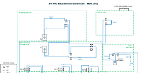
CABIN HEAT A/C COMPRESSORDC/DC CONVERTER HV BATTERY CONTACTORSINVERTER/MOTOR HIGH VOLTAGE DISTRIBUTION SW1 SW4 SW12 SW3 SW11 SW2 SW10 C2 C1 P R D FIRST RESPONDER’S LOOP 400 VDC/12VDC CONVERTER SERVICE DISCONNECT CONTROL PANEL IGN AC HEAT BRAKE GAS 330 Ω IL1 IL2 IL13 IL14 1.8 kΩ IL4 IL3 120 Ω +5V 330 Ω IL5 IL6 330 Ω IL11 IL12 330 Ω IL10IL9 330 Ω IL7 DC1 IL8 DC2 + - SW5 SW6 12 VDC BATTERY 330 Ω REV 8 EV-400 Educational Schematic - HVIL only © ConsuLab Educatech Inc., 2024. All rights reserved CABIN HEAT A/C COMPRESSORDC/DC CONVERTER HV BATTERY CONTACTORSINVERTER/MOTOR HIGH VOLTAGE DISTRIBUTION SW1 SW4 SW12 SW3 SW11 SW2 SW10 C2 C1 P R D FIRST RESPONDER’S LOOP 400 VDC/12VDC CONVERTER SERVICE DISCONNECT CONTROL PANEL IGN AC HEAT BRAKE GAS HV13 HV14 SMR3 SMR2 SMR1 HV1 HV2 HV4 HV15HV16 HV3 HV11 HV12HV9 HV10 HV5 HV6 HV7 HV8 U V W N INVERTER 200V Battery 200V Battery REV 8 EV-400 Educational Schematic - HV only © ConsuLab Educatech Inc., 2024. All rights reserved CABIN HEAT A/C COMPRESSORDC/DC CONVERTER HV BATTERY CONTACTORSINVERTER/MOTOR HIGH VOLTAGE DISTRIBUTION SW1 SW4 SW12 SW3 SW11 SW2 SW10 C2 C1 P R D SERVICE DISCONNECT CONTROL PANEL FIRST RESPONDER’S LOOP 400 VDC/12VDC CONVERTER IGN AC HEAT BRAKE GAS HV13 HV14 SMR3 SMR2 SMR1 HV1 HV2 HV4 HV15HV16 HV3 HV11 HV12HV9 HV10 HV5 HV6 HV7 HV8 U V W N INVERTER 200V Battery 200V Battery 330 Ω IL1 IL2 IL13 IL14 1.8 kΩ IL4 IL3 120 Ω +5V 330 Ω IL5 IL6 330 Ω IL11 IL12 330 Ω IL10IL9 330 Ω IL7 DC1 IL8 DC2 + - SW5 SW6 12 VDC BATTERY 330 Ω REV 8 EV-400 Educational Schematic - HV & HVIL © ConsuLab Educatech Inc., 2024. All rights reserved CABIN HEAT A/C COMPRESSORDC/DC CONVERTER HV BATTERY CONTACTORSINVERTER/MOTOR HIGH VOLTAGE DISTRIBUTION SW1 SW4 SW12 SW3 SW11 SW2 SW10 C2 C1 P R D 400 VDC/12VDC CONVERTER SERVICE DISCONNECT CONTROL PANEL FIRST RESPONDER’S LOOP INVERTER IGN AC HEAT BRAKE GAS 182 kΩ F4 182 kΩ F5 182 kΩ F9 182 kΩ F10 182 kΩ F3 F1 F2 F6: DOES NOT GENERATE 13.5 V F11: FAULTY CABLE F8: SMR3 STUCK ON F7: SMR2 DOES NOT ENGAGE HV13 HV14 SMR3 SMR2 SMR1 HV1 HV2 HV4 HV15HV16 HV3 HV11 HV12HV9 HV10 HV5 HV6 HV7 HV8 U V W N 200V Battery 200V Battery 330 Ω IL1 IL2 IL13 IL14 1.8 kΩ IL4 IL3 120 Ω +5V 330 Ω IL5 IL6 330 Ω IL11 IL12 330 Ω IL10IL9 330 Ω IL7 DC1 IL8 DC2 + - SW5 SW6 12 VDC BATTERY 330 Ω REV 8 Teacher copy EV-400 Educational Schematic - HV & HVIL with Faults © ConsuLab Educatech Inc., 2024. All rights reserved Fault # Description Activation Fault indicator 12V fault interlock fault isolation fault HV fault 1 HVIL short in the inverter 2 wires IL13-IL14 Instant on (IGN Ready) X X 2 HVIL open circuit DC/DC converter IL7-IL8 Instant on (IGN Ready) X X 3 Isolation fault 400V+ HV5 circuit to GND HV distribution Instant on (IGN Ready) X X 4 Isolation fault 400V+ HV13 circuit to GND Inverter/motor Only when in FWD or REV (IGN Ready) X X 5 Isolation fault 400V+ HV9 circuit to GND SW11-SW3 Instant on (IGN Ready) X X 6 DC/DC does not generate 13.5 volts in ready mode Instant on (IGN Ready) X 7 Contactor HV, SMR2 does not engage Instant on (IGN Ready) X 8 Contactor HV stuck ON, positive (SMR3 on neg pole) IGN ON to OFF X 9 Isolation fault 400V+ HV9 circuit to GND PTC Only when heater is activated X X 10 Isolation fault 400V+ HV11 circuit to GND A/C compressor Only when A/C is activated X X 11 Faulty harness between C1 and C2 open HVIL loop When faulty harness installed X X Teacher copy EV-400 Faults List and Description
EM-2000-YF_053330-96_V2023-4.pdf
Instructors manual for EM-2000-YF_053330 Air conditioning system trainer with H-block, R1234YF EM-2000-YF_053330-96_V2023-4 © ConsuLab Educatech Inc, 2023. All rights reserved. EM-2000-YF_053330-96 Table of contents 400-6330 Zéphirin-Paquet St. Québec QC G2C 0M3 Canada consulab.com info@consulab.com Toll-free: +1 (800) 567-0791 USA: +1 (810) 222-4525 Canada: +1 (418) 688-9067 Fax: +1 (418) 843-3444 3 © ConsuLab Educatech Inc, 2023. All rights reserved. No part of this work may be reproduced or transmitted in any form by any means, electronic, mechanical, including photocopying and recording, or by any information storage or retrieval system, without written permission from the publisher. Printed in Canada. Table of contents SA-1 Component Identification Instructor’s answer key 4 TXV & H-Block Operation Older thermostat expansion valve (TXV) – (capillary tube type) 5 H-Block 6 H-Block operation cutaway view 7 Typical internal heat exchanger (IHX) 8 SA-2 TXV & H-Block Operation Instructor’s answer key 9 SA-3 Refrigerant Cycle Refrigerant cycle 10 Instructor’s answer key 11 Study Questions Instructor’s answer key 12 Suggested Instructional Activities 13 consulab.com info@consulab.com 4 EM-2000-YF_053330-96 SA-1 Component Identification SA-1 Component Identification — Answers NOTE : During this activity, engaging students through the use of magnetic cards is particularly effective when it comes time for correction 1. Condenser “IN” digital thermometer 2. Condenser “OUT” digital thermometer 3. High side pressure gaugeI 4. Low side pressure gauge 5. Evaporator “IN” digital thermometer 6. Evaporator “OUT” digital thermometer 7. Condenser 8. Evaporator 9. Condenser “MID-WAY” sight glass 10. Condenser inlet sight glass 11. Evaporator “MID-WAY” sight glass 12. High side service port 13. Low side service port 14. Condenser outlet sight glass 15. H-Block (TXV) “OUT” to compressor sight glass (low-side) 16. H-Block (TXV) “IN” from evaporator sight glass (low-side) 17. Low side restriction valve 18. Receiver drier 19. Receiver drier refrigerant level sight glass 20. High side restriction valve 21. H-Block (TXV) “IN” from receiver drier sight glass (high-side) 22. H-Block (TXV) 23. H-Block (TXV) “OUT” to evaporator (low-side) 24. Cycling switch bypass toggle switch 25. Internal heat exchanger (IHX) consulab.com info@consulab.com 5 EM-2000-YF_053330-96 TXV & H-Block Operation TXV & H-Block Operation The H-Block is becoming a very popular component on newer vehicles. The H-Block with TXV operates similarly to the older Thermostat Expansion Valve (TXV). Older thermostat expansion valve (TXV) – (capillary tube type) The older TXV consisted of inlet and outlet passages and was normally located on the inlet line of the evaporator. The TXV had a sensing bulb connected to the TXV by a capillary tube. The sensing bulb was attached to the outlet line of the evaporator and sealed with insulation. The sensing bulb sensed the temperature of the evaporator outlet pipe which in turn either opened or closed the TXV to prevent evaporator flooding. Problems occurred with the insulation, dirt and corrosion on the connection of the bulb to the outlet line which affected the TXV’s operation. The main advantage of having a H-Block with TXV is that there is no longer a capillary tube and sensing bulb used and the H-Block senses both evaporator pressure and temperature at the evaporator outlet. consulab.com info@consulab.com 6 EM-2000-YF_053330-96 TXV & H-Block Operation H-Block The H-block TXV is connected to both the inlet and outlet lines of the evaporator. It is the dividing point in the system from the high and low pressure sides. The high-pressure liquid line from the condenser is connected to the H-Block inlet. The high-pressure liquid refrigerant is metered through an orifice controlled by a ball valve held closed by the calibration spring. The other side of the block is connected to the low pressure or suction side of the system (evaporator outlet). It has a sensing element that transfers some of the absorbed heat of the refrigerant to the power element (diaphragm). The power element contains an independent small charge of refrigerant. The refrigerant in the power element is heated by the temperature of the refrigerant, which causes the internal pressure to rise against the diaphragm and pushes on the valve pin. Evaporator pressure is present on the opposite side of the diaphragm and will act in conjunction with the calibration spring against the pressure in the power element. The pressure continues to rise unseating the ball by over- coming the calibration spring and evaporator pressure. As the evaporator is saturated with refrigerant, the sensor cools and the pressure in the power element against the diaphragm lowers. The valve is then closed by the calibration spring. In normal operation, the H-block continually meters the amount of refrigerant flowing into the evaporator by the move- ment of the ball valve. This provides the desired evaporator temperature for all operating conditions. consulab.com info@consulab.com 7 EM-2000-YF_053330-96 TXV & H-Block Operation H-Block Operation Cutaway ViewH-BLOCK (TXV) OPERATION CUTAWAY VIEW EVAPORATOR REFRIGERANT VAPOR FROM EVAPORATOR OUTLET TO H-BLOCK REFRIGERANT VAPOR LEAVING H-BLOCK ENTERING COMPRESSOR LIQUID REFRIGERANT FROM RECEIVER/DRIER ENTERING H-BLOCK SENSING HALF (Vapor side of H-Block (TXV) OPERATING HALF (Liquid side of H-Block (TXV) REFRIGERANT ENTERING THE EVAPORATOR AS A LOW PRESSURE LIQUID/DROPLET STATE SENSING ELEMENT BALL VALVE & SPRING VALVE PIN consulab.com info@consulab.com 8 EM-2000-YF_053330-96 TXV & H-Block Operation Internal Heat Exchanger (IHX) The IHX is installed in the system to further subcool the liquid refrigerant in the high pressure side of the system. This increases the effi ciency of the system and reduces the amount of refrigerant required. The liquid refrigerant leaving the receiver drier enters the outer portion of the IHX and fl ows through the IHX and exits the opposite end. The refrigerant will further decrease in temperature prior to entering the H block TXV. On the low pressure side of the system the vaporized refrigerant leaving the H Block TXV will enter the inner portion of the IHX. As the refrigerant passes through the tube it will absorb heat from the high side refrigerant in the outer tube. This will further superheat the vapor on the low side in addition to cooling the high side refrigerant. Typical internal heat exchanger (IHX) consulab.com info@consulab.com 9 EM-2000-YF_053330-96 TXV & H-Block Operation SA-2 TXV & H-Block Operation — Answers 1. G 2. E 3. B 4. C 5. A 6. D 7. F 8. G 9. E 10. E 11. B 12. G 13. E consulab.com info@consulab.com 10 EM-2000-YF_053330-96 SA-3 Refrigerant Cycle SA-3 Refrigerant Cycle EM -2000-YF_053330 Refrigerant flow diagram 6 7 consulab.com info@consulab.com 11 EM-2000-YF_053330-96 SA-3 Refrigerant Cycle SA-3 Refrigerant Cycle — Answers Using your own words, describe the refrigerant flow cycle of a typical H-Block TXV system using R1234yf. Include descriptions of high or low pressures, liquid or vapor and high or low temperature for the refrigerant in various parts of the system. Begin your description at the compressor outlet. Compressor outlet : The refrigerant leaves the outlet of the compressor as a hot vapor under high pressure and tem- perature. This pressure increase raises the boiling point and temperature of the refrigerant. Condenseur : The refrigerant then flows into the inlet fitting of the condenser which is at the top of the condenser. The refrigerant then flows through the condenser tubes where it is cooled and condensed into a liquid by the ambient air blowing through the condenser. The liquid refrigerant will continue to decrease in temperature and is sub-cooled. The refrigerant is now a warm liquid under high pressure. Receiver drier : The refrigerant enters the receiver drier as a warm liquid under high pressure. It flows by a desiccant where any moisture is removed. Refrigerant is stored in the receiver/drier. The warm liquid exits the receiver drier and enters the Internal Heat Exchanger (IHX). The refrigerant is further cooled and exits the IHX and continues to the lower side of the H-Block inlet fitting as a warm high pressure liquid refrigerant. Internal heat exchanger (IHX) : The IHX is connected to both the low-pressure side and the high-pressure side of the system. The high-pressure side refrigerant leaving the receiver drier passes through the outer portion of the IHX prior to entering the H-block. The low-pressure side refrigerant passes through the inner portion of the IHX after leaving the H-block and entering the compressor. The effect of the different states of refrigerants passing through the IHX is further sub-cooling of the high-pressure liquid and increased super-heating of the low pressure vapor. H-Block : Refrigerant from the IHX enters the H-Block as a warm high pressure liquid. There is a restriction in the H-Block that the refrigerant must pass through. The restriction causes a lower pressure of the refrigerant that produces a change of state into a liquid/droplet combination as it absorbs heat. The H-Block monitors the flow of refrigerant through the evaporator and senses the temperature and pressure of the refrigerant leaving the evaporator. The H-Block constantly modulates the flow of refrig- erant into the inlet of the evaporator based on the temperature and pressure of refrigerant leaving the evaporator. Evaporator : Refrigerant enters the inlet fitting at the bottom of the evaporator. After flowing through the restriction of the H-Block, the refrigerant changes state into a low pressure liquid/droplet combination. As refrigerant enters the evaporator, it “boils” because of its lower pressure and boiling point. As it boils, it absorbs heat from the fins of the evaporator. Air blowing across the evaporator fins is cooled. The refrigerant vapor will continue to absorb heat and is super-heated. Refrigerant leaves the evaporator in the outlet fitting at the top of the evaporator as a low pressure vapor. The refrigerant then enters the low side of the Internal Heat Exchanger (IHX). Compressor inlet : Refrigerant enters the inlet side of the compressor as a low temperature/low pressure vapor. The compressor compresses the refrigerant into a high pressure/high temperature gas and the process starts all over again. consulab.com info@consulab.com 12 EM-2000-YF_053330-96 Study Questions Study Questions — Answers 1. A B C D 2. A B 3. A B C D 4. A B C D 5. A B C D 6. A B C D 7. A B C D 8. A B C D 9. A B C D 10. A B C D 11. A B C D 12. A B 13. A B C D 14. A B C D 15. A B C D 16. A B C D 17. A B C D consulab.com info@consulab.com 13 EM-2000-YF_053330-96 Suggested Instructional Activities Suggested Instructional Activities The Consulab EM-2000-YF air conditioning trainer can be utilized in many ways to teach students the TXV (thermostatic expansion valve) air conditioning system. Below are a few suggestions for instructors to best utilize this product. • Allow trainer to stabilize a few minutes after startup before using. • Separate R1234yf manifold gauges can be installed at the high and low side service ports. • Recovery/Recycling machines can be easily installed on the trainer using service ports. • The high and low side ball valves can be used to create partial restrictions or blockages which allows students to observe accumulator reaction, gauge pressure and temperature changes. • Evaporator and Condenser fan speeds can be adjusted to create various operating conditions including restricted condenser and evaporator. CAUTION : Operating the trainer with the condenser fan shut off will result in a rapid increase in high side pressures. Do not operate the trainer for long periods of time with condenser fan off. • Assign included student activity assignments as required. (Test, Word Matching and Essay). • Compressor cycling switch can be switched OFF and the evaporator cooling fan can be switched OFF to simulate a defective compressor control circuit. With both devices turned OFF, the evaporator pressure/temperature will begin to drop and perhaps cause evaporator freezing on outside of fins especially in humid environments. CAUTION: Creating a refrigerant leak anywhere on the trainer is not environmentally acceptable and could damage the trainer resulting in the voiding of product warranty. consulab.com info@consulab.com 14 EM-2000-YF_053330-96 Notes Notes 400-6330 Zéphirin-Paquet St. Québec QC G2C 0M3 Canada © ConsuLab Educatech Inc, 2023. All rights reserved. SA-1 Component identification Instructor’s answer key TXV & H-Block operation Older thermostat expansion valve (TXV) – (capillary tube type) H-Block H-Block operation cutaway view Typical internal heat exchanger (IHX) SA-2 TXV & H-Block operation Instructor’s answer key SA-3 Refrigerant cycle Refrigerant cycle Instructor’s answer key Instructor’s answer key Suggested instructional activities
93-EM-2000-YF_operation-manual_REVA.pdf
Operation manual for EM-2000-YF_053330 Air conditioning system trainer with H-block, R1234YF 93-EM-2000-YF_REVA © ConsuLab Educatech Inc, 2024. All rights reserved. Scan this QR code for: Operation Manual Teacher Resources https://www.consulab.com/customer-space https://www.consulab.com/customer-space 93-EM-2000-YF Table of contents 400-6330 Zéphirin-Paquet St. Québec QC G2C 0M3 Canada consulab.com info@consulab.com Toll-free: +1 (800) 567-0791 USA: +1 (810) 222-4525 Canada: +1 (418) 688-9067 Fax: +1 (418) 843-3444 3 © ConsuLab Educatech Inc, 2024. All rights reserved. No part of this work may be reproduced or transmitted in any form by any means, electronic, mechanical, including photocopying and recording, or by any information storage or retrieval system, without written permission from the publisher. Printed in Canada. The content of this manual is applicable to models 053330 and above. Table of Contents EM-2000-YF-95 Student Assignments — Table of Contents 4 EM-2000-YF-96 Instructor Guide — Table of Contents 4 EM-2000-YF Air conditioning system trainer components 5 Front Panel Components 5 Rear Panel Components 6 EM-2000-YF_053330 Educational objectives 7 EM-2000-YF_053330 Features 7 EM-2000-YF_053330 Specifications 7 Trainer operation and startup 8 Notes 8 Cautions 8 consulab.com info@consulab.com 4 93-EM-2000-YF Teacher Resources Scan this QR code for: Operation Manual Teacher Resources https://www.consulab.com/customer-space EM-2000-YF-95 Student Assignments — Table of Contents EM-2000-YF-96 Instructor Guide — Table of Contents EM-2000-YF-95_V2023-2 Table of contents 400-6330 Zéphirin-Paquet St. Québec QC G2C 0M3 Canada consulab.com info@consulab.com Toll-free: +1 (800) 567-0791 USA: +1 (810) 222-4525 Canada: +1 (418) 688-9067 Fax: +1 (418) 843-3444 3 © ConsuLab Educatech Inc, 2023. All rights reserved. No part of this work may be reproduced or transmitted in any form by any means, electronic, mechanical, including photocopying and recording, or by any information storage or retrieval system, without written permission from the publisher. Printed in Canada. Table of contents SA-1 Student assignement Component identification 4 Student answer sheet 5 TXV & H-Block operation Older thermostat expansion valve (TXV) – (capillary tube type) 6 H-Block 7 H-Block operation cutaway view 8 Internal heat exchanger (IHX) Typical internal heat exchanger (IHX) 9 SA-2 Student assignement TXV & H-block operation 10 Student answer sheet 11 SA-3 Student assignement Refrigerant cycle 12 Student answer sheet 13 Test Study questions 14 Student answer sheet 17 EM-2000-YF-96_V2023-2 Table of contents 400-6330 Zéphirin-Paquet St. Québec QC G2C 0M3 Canada consulab.com info@consulab.com Toll-free: +1 (800) 567-0791 USA: +1 (810) 222-4525 Canada: +1 (418) 688-9067 Fax: +1 (418) 843-3444 3 © ConsuLab Educatech Inc, 2023. All rights reserved. No part of this work may be reproduced or transmitted in any form by any means, electronic, mechanical, including photocopying and recording, or by any information storage or retrieval system, without written permission from the publisher. Printed in Canada. Table of contents SA-1 Component identification Instructor’s answer key 4 TXV & H-Block operation Older thermostat expansion valve (TXV) – (capillary tube type) 5 H-Block 6 H-Block operation cutaway view 7 Typical internal heat exchanger (IHX) 8 SA-2 TXV & H-Block operation Instructor’s answer key 9 SA-3 Refrigerant cycle Refrigerant cycle 10 Instructor’s answer key 11 Test Instructor’s answer key 12 Suggested instructional activities 13 https://www.consulab.com/customer-space consulab.com info@consulab.com 5 93-EM-2000-YF EM-2000-YF Air conditioning system trainer components EM-2000-YF Air conditioning system trainer components Front Panel Components The Consulab EM-2000-YF Air Conditioning System Trainer with H-Block and R1234yf includes the following front panel components : 1. Condenser “IN” digital thermometer 2. Condenser “OUT” digital thermometer 3. High pressure gauge 4. Low pressure gauge 5. Evaporator “IN” digital thermometer 6. Evaporator “OUT” digital thermometer 7. Condenser 8. Evaporator 9. Condenser “MIDWAY” sight glass 10. Condenser “IN” sight glass 11. Evaporator “mid-way” sight glass 12. High side service port 13. Low side service port 14. Condenser “OUT” sight glass 15. H-block “OUT” to compressor sight glass (low-side) 16. H-block “IN” from evaporator sight glass (low-side) 17. Low side restriction valve 18. Receiver/drier 19. Receiver/drier refrigerant level sight glass 20. High side restriction valve 21. H-block “IN” from receiver/drier sight glass (high-side) 22. H-Block 23. H-Block “OUT” to evaporator (low-side) 24. Cycling switch bypass toggle switch 25. Internal Heat Exchanger (IHX) 1 2 3 4 5 6 8 11 24 13 17 16 232221152520 19 18 14 12 9 10 7 consulab.com info@consulab.com 6 93-EM-2000-YF EM-2000-YF Air conditioning system trainer components Rear Panel Components The EM-2000-YF, Air Conditioning System Trainer with H-Block and R1234yf includes the following rear panel components : 1. Evaporator 3-speed fan switch 2. Cycling Switch Bypass with Toggle Switch 3. Low side suction line 4. Condenser 3-speed fan switch (Fan 1) 5. Electrical junction box. WARNING: Do not open. 6. Compressor 7. High side discharge line 8. High pressure cut-off switch WARNING: Opens at 300 psi and closes at 200 psi to protect the system from excessive pressures. 9. Condenser 3-speed fan switch (Fan 2) 10. Power switch with 12V protection fuse 1 2 3 4 9 865 10 7 consulab.com info@consulab.com 7 93-EM-2000-YF Educational objectives, features, specifications EM-2000-YF_053330 Educational objectives • Trainer has all major components required for an automotive air conditioning system using the H-Block TXV system. • Fully operational with typical component layout and organization. • Clear sight glasses provide clear understanding of the H-Block air conditioning refrigeration cycle. • Allows student observation of refrigerant changes of state (liquid/vapor) at the receiver/drier, evaporator and condenser. • Trainer can be connected to any A/C Recycling/Recovery equipment using R1234yf ports. • Allows visual inspection of the role and operation of the H-Block and receiver drier. • Provides pressure and temperature measurement displays of evaporator and condenser. • Is equipped with an Internal Heat Exchanger (IHX) to increase subcooling of the refrigerant. • Allows the introduction of system restrictions and blockages for diagnostic learning. • Adjustable fan speeds for demonstrations of typical performance problems for evaporator and condenser. • Removable magnetic component identification labels and refrigerant flow arrows for student learning. • Equipped with high pressure cut-out switch, evaporator deicing switch and internal compressor protection. • High and low side ball valves can be adjusted to demonstrate various system restrictions resulting in abnormal operation. • Trainers condenser, evaporator and compressor cycling switches can be adjusted to demonstrate various abnormal symptoms. EM-2000-YF_053330 Features • OEM R1234yf ports. • High and Low side A/C pressure gauges. • Adjustable temperature control switch for evaporator temperature levels. • Digital thermometers (4) at inlet and outlet of evaporator and condenser. • Internally protected hermetically sealed A/C compressor. • A/C compressor has manual starter with internal thermal protection. • High pressure (300psi) safety switch shuts off compressor. • Adjustable 3-speed evaporator (1) and condenser (2) fans. • Cycling switch bypass (toggle switch). • Stainless steel condensate drip pan with drain. • Power “ON” indicator light. • Removable magnetic component name and refrigerant flow arrow labels. • Operation manual (EM-2000-YF-93), student assignments (EM-2000-YF-95) and instructors manual (EM-2000-YF-96) included. EM-2000-YF_053330 Specifications • Operates on a 120V, 15A, 60Hz circuit. • Refrigerant: R1234yf (28 oz or 1.75 lb) (794 g). • Refrigerant oil: 1.5 oz (30.5 g) PAG46 • Sturdy powder coated metal stand with two locking swivel and two fixed casters. • Dimensions: 46” x 30” x 67” (116.8 x 76.2 x 170.1 cm) / 48” x 40” x 69” (121.9 x 76.2 x 170.1 cm) (w/packaging). • Weight: 250 lb (113.6 kg) / 395 lb (179.5 kg) (w/packaging). consulab.com info@consulab.com 8 93-EM-2000-YF Trainer operation and startup Trainer operation and startup Before turning on the trainer, please be sure to carefully follow the below instructions : • Plug the trainer power cord into a 120V 15A wall outlet ; • Set each of the three fans to normal speed (Position 2) using the three speed switches located on the back of each fan ; • Set the two restriction ball valves (#17 & #20) to the open position (valve handle is parallel to the line) ; • Turn on the power switch on the right side panel ; • Wait a few minutes after turning on for the air conditioning system to stabilize before use. Notes 1. The high-pressure safety cut-out switch (#8) located on the rear panel opens at 300 psi and closes at 200 psi. In the unlikely event of excessive system pressure, there will be no loss of refrigerant. 2. The trainer is equipped with an evaporator de-icing switch that will cut out in compressor in the unlikely event of evaporator icing. 3. The EM-2000-YF trainer has 1/4 oz (8g) of refrigerant dye mixed with refrigerant to better show refrigerant flow. 4. The A/C compressor is prefilled with R1234yf refrigerant (28 oz or 1.75 lb) (794 g). 5. The toggle switch (24) on the front panel will bypass the compressor cycling switch and allow the evaporator to become cooler than normal. To demonstrate this symptom, turn the evaporator cooling fan to OFF and open the toggle switch. Cautions 1. Creating a refrigerant leak anywhere on the trainer is not environmentally acceptable and could damage the trainer resulting in the voiding of product warranty. 2. It is our recommendation that no air conditioning system flushing kits be used with your ConsuLab EM-2000 AC System Trainer. The chemicals in some flushing solvents can negatively react with the components that have been installed on the trainer to make the refrigerant visible. 3. When performing a system leak test on this trainer with pressurized nitrogen do not exceed 125 psi (860 kPa). Three Speed Switch Power switch with 12V fuse consulab.com info@consulab.com 9 93-EM-2000-YF Notes Notes consulab.com info@consulab.com 10 93-EM-2000-YF Notes Notes 400-6330 Zéphirin-Paquet St. Québec QC G2C 0M3 Canada © ConsuLab Educatech Inc, 2023. All rights reserved. EM-2000-YF-95 Student Assignments — Table of Contents EM-2000-YF-96 Instructor Guide — Table of Contents EM-2000-YF Air conditioning system trainer components Front Panel Components Rear Panel Components EM-2000-YF_053330 Educational objectives EM-2000-YF_053330 Features EM-2000-YF_053330 Specifications Trainer operation and startup Notes Cautions

Ev-360_spec-sheet_EN_V2025-11.pdf
ADAS (Advanced Driver Assist Systems) Trainer EV-360_053325 Rev. 2025/11 EV-360_053325 ADAS (Advanced Driver Assist Systems) Trainer consulab.com info@consulab.com 400-6330 Zéphirin-Paquet St. Québec QC G2C 0M3 Canada Toll-free: +1 (800) 567-0791 U.S.A.: +1 (810) 222-4525 Canada: +1 (418) 688-9067 Fax: +1 (418) 843-3444 EDUCATIONAL ADVANTAGES FEATURES INCLUDES OPTIONS This exciting new trainer is for teaching the concepts of autonomous vehicle systems & Advanced Driver Assistance Systems (ADAS). The EV-360 was de- signed to demonstrate the fundamental concepts and technologies currently incorporated in today’s advanced vehicles. This trainer allows a student to visualize sensor readings and results, literally locating where the components are on a vehicle and compares the strengths and weaknesses of the vari- ous sensors andtechnologies to one another. The student becomes the processor of all the sensor inputs to experience “sensor fusion”, or the process of interpreting all this information into a desired outcome or reaction. ADAS sensor calibration can also be demonstrated as well as front camera object detect/identification. The EV-360 can be used in conjunction with real vehicles as it augments actual on-car learning. • The trainer is a scale model, providing the visual cues of where most ADAS components are typically found on an actual vehicle, helping the students to recognize design function and orientation. • It incorporates a 10” X 6” tablet display with EXPLORE or DRIVE mode viewing options. These choices allow either an overall view of a composite vehicle illustrating the location of all the ADAS sensors or individual views of each of the following components live data operation : - Front Camera Adjustable - LiDAR Adjustable - Front Radar Adjustable - Ultrasonic Sensors (L/F) Non-adjustable - Ultrasonic Sensors (R/F) Non-adjustable - Park/Reverse/Drive Selector Adjustable - Steering Wheel Angle Calibration - Driver Presence Demonstrable - Inertial Measurement Unit Adjustable - Blind Spot Radar (L/S) Adjustable - Blind Spot Radar (R/S) Adjustable - Rear Camera Adjustable - Ultrasonic Sensors (L/R) Non-adjustable - Ultrasonic Sensors (R/R) Non-adjustable • Power Cord • Student assignement kit - Magnetic gravoplys for component ID student assignment - Plum Bob - Colored Chalks - Protractor - Mason’s Line • Camera object ID samples (street signs, photos, etc) *available from website • EV-360 Storage Case • EV-360-10_053361 Mobile stand for EV-360 EV-360_053325 ADAS (Advanced Driver Assist Systems) Trainer consulab.com info@consulab.com 400-6330 Zéphirin-Paquet St. Québec QC G2C 0M3 Canada Toll-free: +1 (800) 567-0791 U.S.A.: +1 (810) 222-4525 Canada: +1 (418) 688-9067 Fax: +1 (418) 843-3444 Scan this QR code for more about this product TECHNICAL INFORMATIONS APPLICATION FOR HEAVY VEHICLE • Application : Composite Vehicle • Dimensions : 16 1/8 W x 38 9/16 L x 13 7/16 H inch (40.95 W x 97.95 L x 34.13 H cm) 20 1/8 W x 42 9/16 L x 17 7/16 H inch (51.12 W x 108.11 L x 44.29 H cm) with packaging • Weight : 52 lbs (23.58 kg) / 62 lbs (28.12 kg) with packaging • Power supply : 120VAC / 3 Amps • Video Output port : HDMi This table clearly shows that the EV-360 incorporates technologies similar to those used in modern trucks and buses, making it a realistic and relevant platform for training and develop- ment in this field. Ke nW or th / B en di x W in gm an F us io n Pe te rb ilt / B en di x W in gm an F us io n M ac k /B en di x W in gm an F us io n In te rn at io na l® / B en di x W in gm an F us io n M C I / B en di x W in gm an F us io n Bl ue bi rd / B en di x W in gm an Vo lv o / V ol vo A ct iv e D ri ve r A ss is t ( VA D A ) Pr ev os t / V ol vo A ct iv e D ri ve r A ss is t ( VA D A ) M er ce de s / D et ro it A ss ur an ce Fr ei gh tl in er / D et ro it A ss ur an ce W es te rn S ta r / D et ro it A ss ur an ce M A N / T ra ffi c Ja m A ss is t Te sl a Se m i / T es la A ut op ilo t H IN O / W ab co O ng ua rd Is uz u / M ob ile ye Sc an ia / S m ar t D as h S1: Front Camera S2: LiDAR S3: Front Radar S4: Left/Right Front Ultra- sonic Sensor S7: Steering Wheel Sen- sor S8: Driver Presence Sensor S9: Inertial Measurement Unit S10: Left/Right Side Radar S12: Rear Camera S13: Left Rear Ultrasonic Sensor Data collected in 2025

95-CL-1902_student-assignment_REV_2026.pdf
Student assignments for CL-1902_053242 95-CL-1902_053242 © ConsuLab Educatech Inc, 2025. All rights reserved. Electromagnetism Trainer 400-6330 Zéphirin-Paquet St. Québec QC G2C 0M3 Canada consulab.com info@consulab.com Toll-free: +1 (800) 567-0791 USA: +1 (810) 222-4525 Canada: +1 (418) 688-9067 Fax: +1 (418) 843-3444 2 95-CL-1902 Table of Contents Table of Contents Introduction 4 Teaching Modules 6 Instrumentation 8 Magnetism 12 Electromagnetism 15 Magnetic Field 15 Faraday’s Laws 18 Electromagnetic Solenoid 19 Self-inductance 20 Mutual Induction 21 Automotive Ignition System 22 Right Hand Rule 23 Understanding AC and DC 24 AC Generator Charging System 24 DC Generator 24 Alternator Charging System 27 Motor Operation 30 Module A-1 — Magnetism 33 SA-1 LEVEL 1 33 Exploring Magnetism 33 SA-2 LEVEL 2 35 Current and Magnetic Fields 35 SA-3 LEVEL 3 37 Faraday’s Laws in Coil Circuits 37 Module A-2 — Electromagnetism 39 SA-4 LEVEL 1 39 Reverse Polarity 39 SA-5 LEVEL 2 41 Electromagnetic Solenoid 41 400-6330 Zéphirin-Paquet St. Québec QC G2C 0M3 Canada consulab.com info@consulab.com Toll-free: +1 (800) 567-0791 USA: +1 (810) 222-4525 Canada: +1 (418) 688-9067 Fax: +1 (418) 843-3444 3 95-CL-1902 Table of contents SA-6 LEVEL 3 43 Solenoid/ Actuator 43 Module A-1 and Module A-2 Student Assessments 45 Module B-1 and module B-2 47 SA-7 LEVEL 1 47 Self-Inductance 47 SA-8 LEVEL 2 50 Exploring Coil Interaction 50 SA-9 LEVEL 3 53 Measuring Mutual Inductance 53 Module C — Automotive Ignition 55 SA-10 LEVEL 1 55 Center Core Behavior 55 SA-11 LEVEL 2 57 Polarity and Induction 57 SA-12 LEVEL 3 59 Magnetic Field Collapse Effect 59 Module B-1, B-2 and C Student Assessment 62 Module D — Right Hand Rule 66 SA-13 LEVEL 1 66 Applying Lenz’s Law 66 SA-14 LEVEL 2 67 Magnetic Field Orientation 67 SA-15 LEVEL 3 69 Determining Flux Direction 69 Module D Student Assessment 72 Module E — AC Generation 74 SA-16 LEVEL 1 74 Rotor Current Action 74 SA-17 LEVEL 2 76 Half-Wave Rectification 76 SA-18 LEVEL 3 78 Full-Wave Rectification 78 Module E Student Assessment 80 400-6330 Zéphirin-Paquet St. Québec QC G2C 0M3 Canada consulab.com info@consulab.com Toll-free: +1 (800) 567-0791 USA: +1 (810) 222-4525 Canada: +1 (418) 688-9067 Fax: +1 (418) 843-3444 4 © ConsuLab Educatech Inc, 2023. All rights reserved. No part of this work may be reproduced or transmitted in any form by any means, electronic, mechanical, including photocopying and recording, or by any information storage or retrieval system, without written permission from the publisher. Printed in Canada. The content of this manual is applicable to models 053242 and above. 95-CL-1902 Table of contents Module F-1 and module F-2 83 SA-19 LEVEL 1 83 F-1 Motor Operation (3 pages) 83 SA-20 LEVEL 2 86 Motor Design and Direction 86 SA-21 LEVEL 3 88 Motoras a Generator 88 Module F-1 and F-2 Students Assessments 92 Glossary 95 consulab.com info@consulab.com 5 95-CL-1902 Introduction Introduction The CL-1902_053242 Electromagnetism Trainer is designed to teach the principles of magnetism and electromagnetism to demonstrate magnetic fields (Flux, Flux Lines, Lines of Force), how they are generated, and what automotive com- ponents use these principles. This curriculum is designed for self-directed learning, allowing students to independently follow the material and master these principles. They will learn to build magnetic lines of force circuits for CL-1902 Modules A-1, A-2, B-1 and B-2, and to describe what takes place when current and voltage are applied to a coil of wire. Modules B-1, B-2, and C will allow students to learn about self and mutual inductance. Module D demonstrates a working model of the Right Hand Rule. This section explains what occurs when a magnet passes through a coil of wire, illustrating Michael Faraday’s Laws of Electromagnetic Induction. It establishes the connection between magnetism and the operation of solenoids, motors, and generators. Module E explores how electromagnetism produces current in an AC generator, while Module F allows students to investigate the principles behind electric motor operation. Introduction summary The CL-1902 Electromagnetism Trainer allows you to learn the principles of magnetism and electromagnetism, neces- sary for performing useful work in electric vehicule and electronic system applications. Through each module, you will be able to understand and observe: • Magnetic fields • Feeling the attraction and repel of magnetic fields • Self inductance and mutual inductance • Right Hand Rule • Faraday’s laws • The link between magnetism and the operation of solenoids, motors, and generators consulab.com info@consulab.com 6 95-CL-1902 Introduction CRI Intructional Strategies • Performance Objectives – A precise description of the expected outcomes and the criteria for evaluating them, clearly defining what learners need to master. • Contextual Teaching/Learning Media – Demonstrate completion of the learning objectives by constructing the 21 student assignments at 3 levels in Modules A to F along with group discussions, and other available material. • Criterion Referenced Testing – Evaluation of learning in terms of the knowledge/skills specified in the learning ob- jectives. • Laboratory Experiences will be found through the completion of the 21 student assignments. Power Supply Adapter Rods Jumper Wires E F-2F-1 C B-2 B-1 D A-2 A-1 Magnetic Field Indicator Compass Power Supply unit consulab.com info@consulab.com 7 95-CL-1902 Teaching Modules Teaching Modules Module A-1 : A coil of wire to demonstrate how a current carrying conductor creates a magnetic field. The two ends of the coil are connected to the blue and yellow receptacles. Module A-2 : A coil of wire to demonstrate how a current carrying conductor creates a magnetic field, wound in the opposite direction than that of A-1, to demonstrate how the direction of windings affects the magnetic field generated. The two ends of the coil are connected to the blue and yellow recepta- cles. Module B-1 : A single coil of wire with an open core. It is identical to Module A-2. The two ends of the coil are connected to the blue and yellow receptacles. There is a red and green diode connected between the two receptacles. The diodes are connected with opposite polarities. The diodes are used to show induced voltage polarities. Module B-2 : A single coil of wire with an open core. This module demonstrates mutual induction by showing how electricity is transferred from one coil to another using an iron core. B-2 has ½ the number of turns as B-1. There is a physical gap between B-1 & B-2. The two ends of the coil are connected to the blue and yellow receptacles. There is a red and green diode connected between the two receptacles. The diodes are connected with opposite polarities. Module C : Demonstrates the increase in induction efficiency when one coil is put within another and uses an iron core. Two coil’s of different number of turns with the left coil able to be moved back and forth inside the right coil. The two ends of each coil are connected to the blue and yellow recep- tacles. There is a red and green diode connected between each coil’s two receptacles. The di- odes are connected with opposite polarities. The left hand coil has several iron core rods located inside the core. consulab.com info@consulab.com 8 95-CL-1902 Teaching Modules Module D : Demonstrates how a current carrying conductor has a magnetic field generated around it, shows the right-hand rule. Two permanent magnets are positioned between conductive non-magnetic rods. Another conductive non-magnetic movable shaft (axle) lays across the two rods on which two plastic wheels are mounted. One fixed rod is connected to the yellow receptacle and the other is connected to the blue receptacle. Module E : A permanent magnet mounted on a shaft (rotor) that is able to be rotated by a hand wheel crank. A single coil of wire wound stationary but positioned near the rotor with its two ends connected to the blue and yellow receptacles. In addition, a single diode is mounted to the panel with its two ends connected to blue and yellow receptacles. The are four other diodes connected to form a rectifier bridge (Wheat- stone) with two diode junctions connected to blue and yellow receptacles and two other diode junctions connected to red and black receptacles. This module is used to show AC output, full and half-wave rectification. Module F-1 : F-1 is a DC motor with a single pair of commutated sections and one winding. A single coil of wire is wound around an armature (one segment) that can be rotated with a hand wheel crank. The two ends of the coil are each connected to a copper commutator segment mounted on the armature shaft. The segments are electrically insulated from each other. Two brushes ride on the copper commutator segments. Red and black wires are connected to the brushes which are connected to the blue and yellow receptacles. The brushes are mounted in a brush holder that allows manual adjustment of the brush position around the commutator. NOTE : There is a sliding coupler on the right side end of the armature shaft can that be posi- tioned to connect Modules F-1 and F-2 together. Align the flat surface of both shafts before sliding coupler over. F-1 and F-2 can be either driven electrically, manually with a hand crank or can be coupled together. Module F-2 : F-2 is a DC motor with multiple pairs of commutated sections and many windings. Two coils of wire are wound at 90º around an armature (two segments) that can be rotated with a hand wheel crank. Each end of the two coils are connected to a copper commutator segment mounted on the armature shaft. There are a total of four commutator segments. The segments are electrically insulated from each other. The two brushes ride on the commutator against the four segments 90º to each other. Red and black wires are connected to the brushes which are connected to the blue and yellow receptacles. The brushes are mounted in a brush holder that is not adjustable. consulab.com info@consulab.com 9 95-CL-1902 Instrumentation Instrumentation 1. Master ON / OFF 2. Voltmeter 0-15V 3. Bipolar diode 4. 12V / 10V switch 5. Ammeter 0-3A 6. Galvanometer 7. Polarity switch 8. Circuit connection receptacle 9. LED Readout 10. Circuit connection receptacle 11. Power supply adapter and cord 11 1 2 3 4 10 9 8 7 6 5 consulab.com info@consulab.com 10 95-CL-1902 Instrumentation Voltmeter 0-15V – Ammeter 0-3A The power supply voltmeter and ammeter are internally connected to the output receptacles and no further connections are necessary. Galvanometer The galvanometer (micro-ammeter) must be electrically connected in a circuit using its blue and yel- low μA receptacles. It includes a magnetic field viewer with smaller magnets encased to show pres- ence of magnetic field. Bipolar Diode The bipolar diode must be electrically connected in a circuit using its blue and yellow receptacles. 12V / 10V Switch Choice of system voltage either 10 VDC or 12 VDC. Polarity Switch and LED Readouts Power supply + and – output polarities can be manually reversed by the operator. The power supply has a polarity switch which determines the positive and negative of the blue and yellow output receptacles. Yellow LED readouts will indicate the selected polarity. After a period of inactivity (approx. 30 minutes) with the trainer power supply turned on, the LED display window will begin to randomly display the below combination of displays. In this event, simply make an adjustment of polarity switch or cycle the power supply master power button to reset the system. LED Readouts SWITCH IN CENTER POSITION (INDICATES THE POWER SUPPLY IS ON) SWITCH IN LEFT POSITION SWITCH IN RIGHT POSITION The power supply has a POLARITY SWITCH which determines the positive and negative polarities of the blue and yellow output receptacles. Yellow LED readouts will indicator selected polarity. Polarity Switch Positions After a period of inactivity (approx. 30 minutes) with the trainer power supply turned on, the LED display window will begin to randomly display the above combination of displays. In this event, simply make an adjustment of polarity switch or cycle the power supply master power button to reset the system. consulab.com info@consulab.com 11 95-CL-1902 Instrumentation Compass A common compass is used to detect and indicate poles of magnetic fields. NOTE : The red arrow points to the earth’s NORTH pole (magnetic SOUTH pole). The compass is used on the trainer to indicate the magnetic NORTH and SOUTH poles of the module compo- nents and not the earth’s directional NORTH or SOUTH poles. Magnetic Field Indicator A series of small ferrous rods each held within a small captive compartment. The rods will be affected by nearby magnetic fields when brought in close proximity to components on the trainer. Rods One 3 in (8 cm) x 1/2 in (1.25) permanent magnet rod One 5 in (12 cm) x 1/2 in (1.25) aluminum rod (non-ferrous) One 5 in (12 cm) x 1/2 in (1.25) steel rod (ferrous) Jumper Wires Two 32 in (81.3 cm) red wires Two 32 in (81.3 cm) black wires Earth’s North pole MAGNETIC FIELD INDICATOR – A series of small ferrous rods each held within a small captive compartment. The rods will be affected by nearby magnetic fields when brought in close proximity to components on the trainer. MAGNETIC FIELD INDICATOR – A series of small ferrous rods each held within a small captive compartment. The rods will be affected by nearby magnetic fields when brought in close proximity to components on the trainer. Ferrous rods consulab.com info@consulab.com 12 95-CL-1902 Theory Theory consulab.com info@consulab.com 13 95-CL-1902 Magnetism Magnetism In the 17th century, Sir William Gilbert proposed that the Earth functions as a giant magnet with distinct North and South poles. The concept of magnetism was first observed in lodestone, a naturally magnetized mineral, and in the way iron-based metals responded to it. To demonstrate this, Gilbert carved a piece of lodestone (Figure 1) into a spherical shape and showed that when a compass was placed anywhere on its surface, the needle consistently pointed toward the sphere’s North Pole, just like the behavior of a compass on Earth. Lodestone is a naturally magnetized rock made of magnetite, which is an iron oxide mineral. It is ferromagnetic, meaning it can attract certain met- als. Lodestone was used to make the first magnetic compasses, and its name means “leading stone.” When a lodestone is hung so it can move freely, it will turn and point toward Earth’s North Pole. In most materials, the magnetic poles of molecules are arranged randomly, so they don’t create a magnetic force. But in metals like iron, nickel, and cobalt, the molecules can line up so their north poles point one way and their south poles point the other way. This alignment makes the material magnetic. In lodestone, this alignment happens naturally, which is why it acts as a magnet. A magnetic field as shown in Figure 2 is the space surrounding a magnet through which its external lines of force flow. The direction of these lines of force is determined by polarity. Every magnet (Figure 2) has a north and a south pole. Poles behave somewhat like electrical charges. Like poles repel; unlike poles attract (Figures 2 & 3). Inside the magnet it- self, its lines of force travel from south to north. In the space surrounding the magnet, the lines of force move from north to south, returning to the magnet’s southern pole. More lines of force create a stronger magnet. Figure 1 Lodestone Figure 2 The magnetic fields of several different magnets. The magnetic lines of force also called Flux lines or the magnetic field are directional and exit from the North Pole and enter through the South Pole. consulab.com info@consulab.com 14 95-CL-1902 Magnetism A magnet (Figure 3) can be any object or device that attracts iron, steel, and other magnetic materials. There are 3 basic types of magnets : • Natural • Man-made • Electromagnets Magnetism provides a link between mechanical energy and electricity. Electricity and magnetism are linked because any electrical current flowing through a conductor creates a magnetic field. When this conductor is wound into a coil around an iron core, it becomes an electromagnet, or a temporary magnet whose strength depends on the amount of current and number of coil turns. Any conductor moving through a magnetic field creates electrical current. Electricity creates magnetism and magnetism creates electricity. By the use of magnetism, an alternator converts some engine mechanical power to electromotive Force Potential (EMF). Going the other direction, magnetism allows a starter motor to convert electrical energy from the battery into mechanical power to crank the engine. All magnetism is basically electromagnetism in that it results from the kinetic energy of electrons. Whenever an electric current is flowed through a conductor, a magnetic field is created. When a bar shaped permanent magnet is freely sus- pended, the poles tend to point toward the north and south magnetic poles of the earth, like a compass. Figure 4 shows a magnetic field that is made up of many invisible lines of force, called flux lines. These lines are called a magnetic field, magnetic flux or magnetic lines of force. Magnetic flux can be compared to current. Flux lines are directional and EXIT from the North Pole and ENTER through the South Pole. Flux lines are concen- trated at the poles and spread out into the areas between the poles. Magnetic flux is the product of the average magnetic field times the perpendicular area that it penetrates. Flux is used in the operation of solenoids and transformers. In an electric generator where the magnetic field penetrates a rotating coil, the area used in defining the flux is the projection of the coil area onto the plane perpendicular to the magnetic field. Flux density refers to the number of flux lines per unit area. A Gauss gauge can be used to measure a magnetic field. A magnetic field is a vector quantity because it has direction and magnitude. It shows the magnetic influence on moving electric charges, electrical currents, and magnetic materials. A permanent magnet’s magnetic field pulls on magnetic materials such as iron, and attracts or repels other magnets depending on pole alignment. Figure 3 Magnet and Magnetism Figure 4 Magnetic Flux or Magnetic lines of Force surrounding a bar magnet consulab.com info@consulab.com 15 95-CL-1902 Magnetism Magnetism Summary • Flux lines are directional and exit from the magnet’s North Pole and enter through it’s South Pole. • Magnetic lines of flux surrounding a coil look like the ones surrounding a bar magnet. • Flux density or concentration builds the magnetic force. A powerful magnetic field will exhibit a dense flux field, whereas a weak magnetic field will exhibit a low density flux field. • Flux density is always greatest at the poles of a magnet. • Flux lines do not cross each other in a permanent magnet. • Flux lines facing the same direction attract while flux lines facing opposite directions tend to repel. consulab.com info@consulab.com 16 95-CL-1902 Electromagnetism Electromagnetism Magnetism can also be created by an electric current. In the early 19th century, it was discovered that current-carrying conductors were surrounded by a magnetic field. Current flowing through a conductor, such as copper wire, creates a magnetic field around the wire. This effect can be observed by passing a compass lengthwise over a copper wire through which current is flowing as shown in Figure 5 flowing from positive to negative. The needle will deflect from its North-South orientation when this occurs. Current flow through a wire creates a magnetic field around the wire. The greater the current flow the stronger the magnetic field. This type of magnetism created in the space around a conductor by the current flowing through it is called electromagnetism. The magnetic field surrounding a straight, current-carrying conductor consists of several concentric cylinders of flux the length of the wire, Figure 6. The number of magnetic lines of force and how far they spread from the wire determine the strength of the magnetic field. The higher the current flow through the wire, the stronger the magnetic field will be. Electromagnetic Field Rules • Magnetic lines of force or magnetic flux does not move when the current flowing through a conductor remains at a constant value. When current flowing through a con- ductor increases, the magnetic lines of force will extend further away from the conductor. • As current flow increases, the magnitude and strength of magnetic lines of force increase. As current flow decreas- es, they decrease. • As wire length increases, the magnetic field strength de- creases. Wire length is inversely related to magnetic flux. • In automotive electricity and magnetism, we follow the conventional current theory [bold], which flows from pos- itive (+) to negative (-) or ground. To find the direction of magnetic flux lines, we use the right-hand rule [bold] (see Figure 7): Wrap your right hand around the current-car- rying wire with your thumb pointing in the direction of current flow. Your fingers will curl in the direction of the magnetic lines of force. Figure 5 Electromagnetism Magnetic Field + - Figure 6 Concentric circles of magnetic flux surrounding a straight current-carrying conductor, following conventional current flow from positive to negative.. Figure 7 Right Hand Rule for field direction used with Conventional Current Theory consulab.com info@consulab.com 17 95-CL-1902 Electromagnetism In a car or truck, the magnetic field around a conductor that’s straight may be strong enough to interfere with current flow in sensitive nearby circuits, but it’s not enough to do work. The wire must be looped into a coil to concentrate the magnetic field. The more loops or turns in the coil, the stronger your magnetic field. When you place a soft iron core into the looped coil, it becomes a strong electromagnet that can move things. For our study we will use the right hand rule to signify the direction of the magnetic lines of force. Although there is a Left-Hand Rule for electron flow (negative to positive), all assignments will use the Right-Hand Rule. Formula for Electromagnetic Fields As the current (I) increases, the magnetic field (B) gets stronger. As the length (l) of the coiled wire increases, the magnetic field increases. B = Magnetic field strength (in Tesla, T) N = Number of turns in the coil µ = Permeability of the material (how easily it supports a magnetic field) CL-1902 ELECTROMAG TRAINER 31 Right Hand Rule Figure 8 Right Hand Rule for field direction used with Conventional Flow Theory • In automotive electricity and magnetism, it is important to note at this point that we use the conventional theory of current positive to negative or ground (+ to -), we use the right-hand rule to determine the direction of the magnetic flux lines as shown in Figure 8. It states that if you wrapped your right hand around a current-carrying conductor with your thumb pointing in the direction of current flow (positive to negative), your curved fingers would point in the direction of the lines of force. In a car or truck, the magnetic field around a conductor that’s straight may be strong enough to interfere with current flow in sensitive nearby circuits, but it’s not enough to do work. The wire must be looped into a coil to concentrate the magnetic field. The more loops or turns in the coil, the stronger your magnetic field. When you place a soft iron core into the looped coil, it becomes a strong electromagnet that can move things. For our study we will use the right hand rule to signify the direction of the magnetic lines of force. There is also a Left-Hand Rule for the electron-flow theory that is negative to positive. We will be using the Right-Hand Rule in this module. Formula for Electromagnetic Fields 𝐵𝐵 = 𝜇𝜇! 𝑁𝑁 𝑙𝑙 𝐼𝐼 This magnetic field equation is only used to illustrate the relationship between the factors contributing to the magnetic field. • B = magnetic field strength in Tesla • N = number of turns in the coil • µ = this is a constant that represents permeability of the free space • L = Length of the coil wire in meters = Length of the coil wire in meters (m) CL-1902 ELECTROMAG TRAINER 31 Right Hand Rule Figure 8 Right Hand Rule for field direction used with Conventional Flow Theory • In automotive electricity and magnetism, it is important to note at this point that we use the conventional theory of current positive to negative or ground (+ to -), we use the right-hand rule to determine the direction of the magnetic flux lines as shown in Figure 8. It states that if you wrapped your right hand around a current-carrying conductor with your thumb pointing in the direction of current flow (positive to negative), your curved fingers would point in the direction of the lines of force. In a car or truck, the magnetic field around a conductor that’s straight may be strong enough to interfere with current flow in sensitive nearby circuits, but it’s not enough to do work. The wire must be looped into a coil to concentrate the magnetic field. The more loops or turns in the coil, the stronger your magnetic field. When you place a soft iron core into the looped coil, it becomes a strong electromagnet that can move things. For our study we will use the right hand rule to signify the direction of the magnetic lines of force. There is also a Left-Hand Rule for the electron-flow theory that is negative to positive. We will be using the Right-Hand Rule in this module. Formula for Electromagnetic Fields 𝐵𝐵 = 𝜇𝜇! 𝑁𝑁 𝑙𝑙 𝐼𝐼 This magnetic field equation is only used to illustrate the relationship between the factors contributing to the magnetic field. • B = magnetic field strength in Tesla • N = number of turns in the coil • µ = this is a constant that represents permeability of the free space • L = Length of the coil wire in meters = Current in amperes (A) What this means to us as technicians is that the number of turns in the coil and the current through the coil is directly proportional to the magnetic field. So, if you increase the number of turn in the wire or increase the current, the magnet- ic field gets stronger. Loop Conductor Bending the wire into a loop can strengthen the field around a straight conductor. This happens because the magnetic fields from each part of the loop combine at the center, making the field stronger (see Figure 8). The Right Hand Rule also applies to loop conductors. Coil Conductor If several loops of wire are made into a coil, the magnetic flux density is further strengthened. Flux lines around a coil are the same as the flux lines around a bar magnet (Figure 9). They exit from the North Pole and enter at the South Pole. Use the Right Hand Rule to determine the North Pole of a coil. Increasing the number of turns in the wire, by increasing the current through the coil, or both, can strengthen the magnetic field of a coil. CL-1902 ELECTROMAG TRAINER 31 Right Hand Rule Figure 8 Right Hand Rule for field direction used with Conventional Flow Theory • In automotive electricity and magnetism, it is important to note at this point that we use the conventional theory of current positive to negative or ground (+ to -), we use the right-hand rule to determine the direction of the magnetic flux lines as shown in Figure 8. It states that if you wrapped your right hand around a current-carrying conductor with your thumb pointing in the direction of current flow (positive to negative), your curved fingers would point in the direction of the lines of force. In a car or truck, the magnetic field around a conductor that’s straight may be strong enough to interfere with current flow in sensitive nearby circuits, but it’s not enough to do work. The wire must be looped into a coil to concentrate the magnetic field. The more loops or turns in the coil, the stronger your magnetic field. When you place a soft iron core into the looped coil, it becomes a strong electromagnet that can move things. For our study we will use the right hand rule to signify the direction of the magnetic lines of force. There is also a Left-Hand Rule for the electron-flow theory that is negative to positive. We will be using the Right-Hand Rule in this module. Formula for Electromagnetic Fields 𝐵𝐵 = 𝜇𝜇! 𝑁𝑁 𝑙𝑙 𝐼𝐼 This magnetic field equation is only used to illustrate the relationship between the factors contributing to the magnetic field. • B = magnetic field strength in Tesla • N = number of turns in the coil • µ = this is a constant that represents permeability of the free space • L = Length of the coil wire in meters Figure 8 Loop Conductor Figure 9 Coil Conductor consulab.com info@consulab.com 18 95-CL-1902 Electromagnetism Electromagnets The way to strengthen the magnetic field surrounding a current-carrying conductor is to add a soft iron core (Figure 10). Soft iron is very permeable, so magnetic flux lines pass through it easily. If a piece of iron is placed inside a coil conduc- tor, the flux lines concentrate in the iron core, rather than pass through the air. This concentration of force increases the strength of the magnetic field inside the coil and these are called electromagnets. If several loops of wire are made into a coil, the magnetic flux density is further strengthened. Flux lines around a coil are the same as the flux lines around a bar magnet (Figure 11). The Right Hand Rule shows that the thumb points in the direction of current flow (from positive to negative), and the curled fingers indicate the direction of the magnetic field. The magnetic lines of force, or flux, exits from the North Pole and enters at the South Pole. You can use the Right Hand Rule (Figure 12) to determine the north pole of a coil. When using the Right Hand Rule for Coils : You place your right hand over the coil, with your fingers wrapped around the coil in the direction of current flow from positive to negative. Your thumb will then point to the magnetic north of your electromagnet. Increasing the number of turns in the wire, by increasing the current through the coil, or both, can strengthen the magnetic field of a coil. Figure 10 Electromagnets Figure 11 Magnetic field is generated from B to B when current flows through the coil in the direc- tion of the magnetic flux. Figure 12 Right Hand Rule for Coils Thumb Points to North Pole Fingers Around Coil Form POS (+) to NEG (−) Current Flow consulab.com info@consulab.com 19 95-CL-1902 Faraday’s Laws Faraday’s Laws A magnetic field can create an electric current in a conductor if either the conductor or the magnetic field is moving. When a permanent magnet provides the field, this process is called magnetic induction (Figure 13). Imagine a horseshoe magnet with its North Pole on one side and South Pole on the other. Place a steel railroad tie (acting as the conductor) between the poles, and connect a voltmeter with one lead to each end of the tie. If the tie stays still inside the magnetic field, the voltmeter shows zero. There’s no voltage because nothing is moving. Now, shake the railroad tie back and forth inside the magnet’s field. As the tie cuts through the magnetic lines of force, the voltmeter shows a voltage. That means current is flowing! Stop moving the tie, and the current stops. The induced voltage and current can be increased by: • Moving the conductor faster through the magnetic field. • Using more conductor strands (like a coil instead of one tie). • Using a stronger magnet. Electromagnetic Induction Faraday’s Laws This principle is exactly how generators and alternators in cars and trucks produce electricity. Inside an alternator, a magnetic field rotates past coils of wire, cutting through magnetic lines of force and inducing, or creating, current, just like shaking the railroad tie in our example. This process follows Faraday’s Laws of Electromagnetic Induction, which state: • First Law: An EMF (voltage) is induced in a conductor whenever it cuts through magnetic lines of force. • Second Law: The magnitude of the induced EMF depends on the speed of motion, the number of conductors, and the strength of the magnetic field. #1 #2Figure 13 Magnetic Induction consulab.com info@consulab.com 20 95-CL-1902 Electromagnetic Solenoid Electromagnetic Solenoid A solenoid (Figure 14) is a device that uses electromagnetism to produce motion in small, individually controlled back- and-forth movements. However, the typical solenoid produces a lot more holding force than a relay. That means it can do more than close electrical contacts, which is what a relay does. When current flows through a solenoid’s coil, electromagnetism pulls an iron core into the coil; when current stops flow- ing through the coil, the core returns to its base position. These back-and-forth movements of the core can be attached to a rod that is attached to a device like a door lock to move it in two different directions to lock and unlock a vehicle door. The Electromag CL-1902 Coil A-2 along with the steel rod can be used to demonstrate the operation of a solenoid ac- tuator (Figure 15 ) such as an automotive power door lock actuator. The A-2 Coils become electromagnetic coils when power is applied to it. A-1 could also be used to demonstrate this effect but there is not enough room for the metal rod supplied to make the demonstration. Through the use of electromagnetism, the solenoid can draw in the metal rod in one direction and then in the other direction by reversing the polarity. No current - No magnetic field Current flowing — Coil has a magnetic field similar to that of a bar magnet If the current switches direction so does the magnetic field Figure 14 An electromagnetic solenoid is a cylindrical coil of wire acting as a magnet when carrying electric current. The polarity of the coil can be changed to create movement in the other direction AC generator Magnetic Field Line Produced by Current Figure 15 Solenoid Actuator consulab.com info@consulab.com 21 95-CL-1902 Self-inductance Self-inductance Self-inductance is the induction of an EMF in a circuit when the current in that circuit is varied, not constant. It resists or opposes the change of current flowing through it. This occurs due to the self-induced EMF produced in the coil. Self-in- ductance is the induction of a voltage in a current-carrying wire. Lenz’s Law states that this self-induced voltage tends to oppose the current that produces it. If the current continues to increase, the second voltage opposes the increase. When the current stabilizes, the counter voltage is no longer induced because there are no more expanding flux lines (no relative motion). When current to the coil is shut off, the collapsing magnetic flux lines self-induce a voltage in the coil that tries to maintain the original current. The self-induced voltage opposes and slows down the decrease in the original current. The self-induced voltage that opposes the source voltage is called counterelectromotive force (CEMF) or a Back EMF. Just for reference, the equation for Self-Inductance is shown below : E = The EMF generated −L = Self-Inductance measured in Henrys I = change in current in coil t = change in elapsed time When current flows from a battery or alternator (Figure 15) through a coil, the coil builds a magnetic field. If the current changes suddenly, such as when you turn the circuit off, the magnetic field starts to collapse. Because of self-inductance, the coil resists this change by generating a back EMF, which pushes current in the same direction as before. Back EMF acts like inertia [bold] in a car: just as a car resists a sudden stop and keeps rolling forward, the coil resists a sudden change in current. This electrical “inertia” means work [bold] must be done against the back EMF to establish current, and that work is stored as magnetic potential energy [bold], later used to pull in the armature of an automotive solenoid. CL-1902 ELECTROMAG TRAINER 54 Self-Inductance Figure 16 Self-Inductance Self-inductance is the induction of an EMF in a circuit when the current in that circuit is varied not constant. It resists or opposes the change of current flowing through it. This occurs due to the self-induced EMF produced in the coil. Self-inductance is the induction of a voltage in a current-carrying wire. Lenz's Law states that this self-induced voltage tends to oppose the current that produces it. If the current continues to increase, the second voltage opposes the increase. When the current stabilizes, the counter voltage is no longer induced because there are no more expanding flux lines (no relative motion). When current to the coil is shut off, the collapsing magnetic flux lines self-induce a voltage in the coil that tries to maintain the original current. The self-induced voltage opposes and slows down the decrease in the original current. The self-induced voltage that opposes the source voltage is called Counterelectromotive force (CEMF) or a Back EMF. Just for reference, the equation for Self-Inductance is shown below 𝐸𝐸 = −𝐿𝐿 ΔI Δt • E = The EMF generated • -L = Self-Inductance measured in Henrys • I = change in current in coil • t = change in elapsed time Using the above formula as reference, current change from an Alternator or battery (Figure 16) between let’s say the time difference (t) remains constant the number of lines of force measured by a change in current (I) also remain constant. The result is no CEMF created in the coil during this time period. If the current is removed the battery current decreases between t1 and t2. As this current decreases, the magnetic flux lines created by the current also decreases. A CEMF is generated by electromagnetic induction in the coil, which prevents the magnetic flux created by the current from decreasing and the direction of the current due to this CEMF is the same as the EMF generated by the AC generator or battery current. The Back-EMF opposed any change in the current in a circuit. The self-inductance acts as inertia. So, work needs to be done against the Back-EMF in establishing the current. This work done is stored as magnetic potential energy to pull in the armature in an Automotive Solenoid. AC generator Magnetic field line produced by current Figure 15 Solenoid Actuator consulab.com info@consulab.com 22 95-CL-1902 Mutual Induction Mutual Induction When two coils are brought in close proximity to each another the magnetic field in one coil tends to link with the other coil. This generates a voltage within the second coil. This magnetic property of a coil which affects or changes the voltage in another coil is called mutual induction. The changing current in the primary coil creates a changing magnetic flux through the secondary coil that leads to an induced EMF (electromotive force) in the secondary coil. Also, when two coils are close together and connected through a common iron core, energy may be transferred from one to the other through magnetic coupling (Figure 16). Mutual induction means that the expansion or collapse of the magnetic field around one coil induces a voltage in the second coil. Usually, the two coils are wound on the same iron core. One coil winding can be connected to a battery through a switch and is the primary winding. The other coil winding is connected to an external circuit and is called the secondary winding. Mutual inductance is the principle upon which transformers and ignition coils are based. The posi- tions are in Figure 16 : 1. When the switch is open, there is no current in the primary winding. There is no magnetic field and, therefore, no voltage in the secondary winding. 2. When the switch is closed, current is introduced and a magnetic field builds up around both windings. The primary winding thus changes electrical energy from the battery into magnetic energy of the expanding field. As the field expands, it cuts across the secondary winding and induces a voltage in it. A meter connected to the secondary circuit shows current. 3. When the magnetic field has expanded to its full strength, it remains steady as long as the same amount of current exists. The flux lines have stopped their cutting action. There is no relative motion and no voltage in the secondary winding, as shown on the meter. 4. When you open the switch, the primary current stops, and the magnetic field collapses. As it collapses, the magnet- ic flux lines cut across the secondary winding, but in the opposite direction. This induces a secondary voltage with current in the opposite direction, as shown on the voltmeter. Just for reference, the equation for mutual inductance is shown below : E = EMF induced in the B-2 secondary coil −M = Mutual inductance measured in henrys IP = change in current in the primary coil t = change in elapsed time The size of a mutual induced EMF changes in proportion to the changes in current for the number of magnetic lines of force in the primary or B-1 coil in a unit of time. This is multiplied by a constant we will call –M that is determined by the number of windings on Coils B-1 and B-2 along with other factors such as the type of iron used in the steel rod and the orientation of both coils. This information is for reference only. The principle of mutual inductance is used with all trans- formers and the automotive ignition coil. Mutual Induction AC Figure 16 Mutual Induction (Shutterstock) CL-1902 ELECTROMAG TRAINER 69 4. When you open the switch, the primary current stops, and the magnetic field collapses. As it collapses, the magnetic flux lines cut across the secondary winding, but in the opposite direction. This induces a secondary voltage with current in the opposite direction, as shown on the voltmeter. Just for reference, the equation for Mutual-Inductance is shown below E = −𝑀𝑀 Δ𝐼𝐼" Δt • ES = EMF induced in the secondary Coil B2 • -M = Mutual-Inductance measured in Henrys • IP = change in current in the primary coil • t = change in elapsed time The size of a mutual induced EMF changes in proportion to the changes in current for the number of magnetic lines of force in the primary or B1 coil in a unit of time. This is multiplied by a constant we will call –M that is determined by the number of windings on Coils B1 and B2 along with other factors such as the type of iron used in the steel rod and the orientation of the 2 coils. This information is for reference only. The principle of Mutual Inductance is used with all transformers and the automotive ignition coil. AUTOMOTIVE IGNITION SYSTEM Figure 18 Points and Condenser Type Automotive Ignition System The automotive ignition system (Figure 18 works on the principles of electro-magnetic with the ignition coil, which is a step-up transformer operating on the principle of Mutual Inductance. consulab.com info@consulab.com 23 95-CL-1902 Automotive Ingnition System Automotive Ignition System An automotive ignition coil demonstrates mutual inductance because it uses two windings, primary and secondary, like a step-up transformer to boost voltage for the spark plugs. Ignition systems apply battery voltage to the ignition coil positive side and pulse the negative side to ground. When the coil negative lead is grounded, the primary (low voltage) circuit of the coil is complete and a magnetic field is created by the coil windings. When the circuit is opened, the mag- netic field collapses and induces a high voltage in the secondary winding of the ignition coil, which is used to generate a voltage great enough to bridge a gap across the spark plug electrodes creating a spark. The early ignition systems used a set of contact points to make and break the electrical connection to ground. Electronic ignition uses a sensor such as a pickup coil or Hall effect switch to signal an electronic module to make and break the ignition coil primary side ground. When the ignition switch is turned on, voltage should be available at both the positive terminal and the negative termi- nals of the coil. The labeling of positive (+) and negative (−) of the coil indicates that the positive terminal is more pos- itive (closer to battery positive terminal) than the negative terminal of the coil. This is referred to as coil polarity. Coil polarity positive or negative is established by what direction the coil is wound to the left or to the right. The polarity of an ignition coil is determined by the direction of rotation of the coil windings. The correct polarity is then indicated on the primary terminals of the coil.When polarity is reversed, the spark must jump in the opposite direction, from the cooler ground electrode to the hotter center electrode. This is harder for electrons to do, so the ignition system needs about 40% more voltage to overcome that resistance and fire the plug. The coil’s output voltage depends on the ratio of primary to secondary turns, and its winding direction sets the polarity of the terminals, so reversing the leads changes both polarity and spark direction. Ignition Coils The ignition coil creates a high voltage spark by electromagnetic induction. The principle of electro-magnetic induc- tion states that when a magnetic field crosses or cuts across a conductor, a voltage is induced in that conductor. Some automotive ignition coils are true step-up transformers in which the primary and secondary windings are not electrically connected. Spark plug Ignition breaker points Ignition coil Figure 17 Automotive Ignition System) consulab.com info@consulab.com 24 95-CL-1902 Right Hand Rule Right Hand Rule In a conductor like the copper rails in Module D, the lines of force around the copper rails are circular. You can figure out the polarity of the lines of force around a conductor by using the Right Hand Rule (Figures 18 & 19) to determine the direction of the magnetic flux lines. It states that if you wrapped your right hand around a current-carrying conductor with your thumb pointing in the direction of current flow (positive to negative), your curved fingers would point in the direction of the lines of force. In automotive electricity and magnetism, it is important to note at this point that we use the conventional flow theory of current positive to negative or ground (+ to −). The magnetic field around a conductor can be strong enough to perform useful work, such as activating an electric pow- er steering motor in a modern vehicle. To concentrate the magnetic field, the wire can be looped into a coil. The more loops, the stronger the magnetic field. When a soft iron core is inserted into the coil, it becomes a strong electromagnet that can move parts as in a solenoid. Figure 18 Right Hand Rule for field direction used with Conventional Flow Theory Current Flow Magnetic Field + - Figure 19 Right Hand Rule for Magnetic Fields and Current Flow consulab.com info@consulab.com 25 95-CL-1902 AC Generator Charging System & DC Generator Understanding AC and DC Before diving into alternators, it’s important to understand AC and DC current. Alternating Current (AC) changes direc- tion rapidly, alternating between positive (+) and negative (–), while Direct Current (DC) flows steadily in one direction, from the positive (+) terminal to the negative (–) terminal. Most vehicle systems and batteries require DC, but alternators naturally produce AC. To make this usable, a rectifier [bold] converts AC into DC for charging the battery and powering DC vehicle loads. A converter [bold] is used when you need to change one DC voltage level to another, like when step- ping 12V DC down to 5V DC for sensors or control modules. An inverter [bold] is used when AC power is needed from the vehicle’s DC system, like when supplying AC to drive an electric motor in a hybrid vehicle. AC Generator Charging System The alternator (Figure 20), also called an AC generator, is driven by the engine’s crankshaft through a belt to convert mechanical energy into electrical energy. Inside the alternator, the rotor is the rotating component that creates a mag- netic field, and the stator is the stationary set of windings that acts as the conductor. As the rotor spins, its magnetic lines of force cut across the stator windings, inducing voltage through electromagnetic induction. This electrical energy keeps the battery charged and powers the vehicle’s electrical systems. • The name alternator comes from the alternating current (AC) it produces. • AC is converted to direct current (DC) by a diode bridge rectifier [bold] so the battery can stay charged. • The alternator must produce enough electrical energy to recharge the battery and to supply vehicle loads. • The term stator means stationary because its windings do not move, unlike the armature in a DC generator. DC Generator To better understand the alternator, we will look at the early DC generator. It also uses the principle of electromagnetic induction to produce DC current as shown in Figure 21. When the magnetic lines of force crosses or cuts a conductor (wire loop), it induces a voltage in that conductor. The DC generator uses an iron core or laminated iron sheets to create an electromagnet. When current flows through this coil a magnetic field or flux is created between the pole pieces. Permanent magnets could be used. Figure 20 Belt-driven Alternator Figure 21 DC Generator LAMINATED CORE FIELDLINE OF FORCE WIRE LOOP CARBON BRUSH SPLIT RING COMMUTATOR N S consulab.com info@consulab.com 26 95-CL-1902 DC Generator A single wire loop is shown in Figure 22 between the North and South Pole poles. When this wire loop is turned within a magnetic field, it cuts the lines of force and a voltage is induced. When there is a complete circuit from the wire loop, current will flow. Rotor The wire loop is connected to a split ring called a commutator and carbon brushes pick-up electrical energy because the commutator (wire loop) rotates. Wires from the carbon brushes transfer the energy to the load circuit shown as a resistor in Figure 21. When the wire loop completes one full rotation the induced voltage would reverse itself and therefore the current would flow in the opposite direction (AC current) after the initial half-turn. To produce an output in one direction or polarity (DC current), the split-ring commutator is employed. During the second half-turn, the carbon brushes run on commutator segments opposite to the ones over which they slid for the first half-turn keeping the same rotational direction. The output waveform isn’t a steady-level DC, but rises and falls to make a pattern called a pulsating DC. So, for complete 360° turn of the wire loop, two waveforms or a Sine wave is produced. The rotor winding (Figure 23) in an alternator creates a magnetic field, replacing the magnetic windings used in a DC generator. Although the rotor poles keep a small amount of magnetism when not in use, it is too weak to produce volt- age. To strengthen the magnetic field, an excitation or field winding [bold] sends current through the rotor winding, and a voltage regulator controls this current by adding resistance. Inside the rotor winding is a soft iron core that becomes magnetized when current flows, causing the attached pole pieces to take on magnetic polarity. In brush-type alternators, current reaches the rotor winding through slip rings and brushes. The combination of the iron core and steel rotor halves improves the magnetic field’s strength and permeability. Figure 22 DC generator Rotor Stator Figure 23 Alternator Rotor (Field Winding) consulab.com info@consulab.com 27 95-CL-1902 DC Generator Stator The stator in an alternator (Figure 24) is the stationary conductor that replaces the wire-loop commutator of a DC gener- ator. Its windings are laminated to prevent eddy currents in the iron core. Three conductors are wound onto a cylindrical laminated core and assembled as one piece called the stator, which does not rotate like a DC generator’s commutator. Each winding is formed into coils spaced evenly around the core, with as many coils as there are pairs of north and south rotor poles. In a brush-type alternator, carbon brushes ride on two slip rings [bold] and connect to a battery-sup- plied circuit that carries current to and from the stator. The brushes are housed in a holder, and the field current typical- ly ranges from 1.5 to 3.0 amperes. Figure 24 Alternator Exploded View Showing Rotor and Stator Lock Nut Pulley D.E. Pulley D.E. Bearing Stator Grounded Plate 3-Phase Bridge Rectfier Pos. Terminal to Battery 2-Pin Connector Neg. Battery Terminal End Cover Bearing Screw Voltage RegulatorRotor Field Coil Carbon Brushes Slip Rings Air Vents Mounting Screws consulab.com info@consulab.com 28 95-CL-1902 Alternator Charging System Alternator Charging System The alternator charging circuit (Figure 25) consists of a magnet rotating inside a fixed-loop stator, or conductor. The al- ternating current produced in the conductor is rectified by a single diode as in Half-Wave Rectification or multiple diodes in Full-Wave Rectification. In our exercises we did not cover voltage regulation. However, in an automotive alternator, the voltage regulator, limits the field current and thus the alternator output voltage according to the demands of the electrical system. AC Current induces voltage in the stator by rotating magnetic field inside the stationing stator conduc- tor. The greatest AC current output is produced when the rotor is parallel to stator with magnetic field at right angles to stator. The rotor makes a ¼ revolution and is at right angles to stator with magnetic field parallel to stator then the voltage changes to positive peak, then to negative peak, produceing sine wave voltage. The wave shape controlled by angle between magnet and conductor. The voltage regulator (Figure 26) adds resistance in series to the field circuit though a mechanical regulator, an electronic regulator, or by the vehicle engine management computer. Stator Conductor Load Magnetic Field Figure 25 Operation based on rotation of magnetic field inside a fixed-loop conductor Voltage Regulator Figure 26 Voltage Regulation consulab.com info@consulab.com 29 95-CL-1902 Alternator Charging System Half-Wave Rectification A half-wave rectifier transforms AC to DC voltage (Figure 27). The half-wave rectifier circuit used in our exercise con- tained only one diode for the rectification. It is defined as a type of rectifier that allows only one-half cycle of an AC voltage waveform to pass while blocking the other half cycle. Full-Wave Diode Rectifier Bridge The alternator produces AC, which means the current flows in one direction and then reverses every half turn of the rotor. However, vehicle systems and the battery require DC, which flows in only one direction. To convert AC into DC, the charging system uses diodes. A full-wave rectifier bridge [bold] uses multiple diodes arranged in a bridge to allow both halves of the AC wave to be converted into DC, providing a smoother and more efficient output for the battery and electrical systems. Figure 27 One Module E diode used as a half-wave rectifier Figure 28 Four Module E diodes used in a full-wave rectifier consulab.com info@consulab.com 30 95-CL-1902 Alternator Charging System A diode acts is a one-way switch or electrical valve. The diode blocks ½ of the AC voltage (Figure 29). The diode will allow current to flow from X to Y, shown in Frame A. In Frame B, the current cannot flow from Y to X because the diode blocks the current. The first half of the current, from X to Y, was allowed to pass through diode and shown on the graph as ½ sine wave XY. The second half of current, from Y to X, was not allowed to pass through diode. It is not shown on the wave form because it never traveled through the circuit. When voltage reverses at start of next rotor revolution, current is again allowed through diode from XY. When you add additional diodes to the circuit, this allows more AC voltage to be rectified to DC. In Frame A, current moves from X to Y. It travels from X, through Diode #2, through the load, through Diode #3, and back to Y. n Frame B, current moves from Y to X. It travels from Y, through Diode #4, through the load, through Diode #1, and back to X. The current will move through the load in the same direction because the AC has been rectified to DC. The waveform at the bottom of Figure 29 shows the current output of an alternator with one conductor and 4 diodes. There is more current because all of the voltage has been rectified. This is called full-wave rectification. Time Vo lt ag e C ur re nt C U RR EN T FL O W GRAPH C U RR EN T FL O W Figure 29 Full-Wave Diode Bridge Rectifier consulab.com info@consulab.com 31 95-CL-1902 Motor Operation Motor Operation The electromagnet (Figure 30) is created in a loop of wire that is placed between two electromagnetic poles. Motors work on principle of magnetic repulsion. This magnetic repulsion takes place when a straight loop wire conductor is located within a magnetic field and current flows through that wire loop. This situation creates two separate magnetic fields. One produced by the magnet, (poles of the magnetic field winding) and another produced by the current flowing through the conductor. Figure 30 shows the magnet’s magnetic field moving from the S-Pole to N-Pole and conductor’s magnetic field flowing around the conductor. The magnetic lines of force have a rubber band characteristic. The magnetic flux stretches and tries to shorten itself. There is a stronger magnetic field on one side of the looped conductor with a very weak magnetic field on the other side. Then the conductor is repulsed by a strong magnetic field and turns toward the weaker magnetic field. As current in the conductor (the motor armature) and the strength of the magnetic field windings increase, the following effects occur: • More lines of magnetism are created on the strong side. • A greater repulsive force acts on the conductor (armature). • The conductor pushes harder toward the weak side in an attempt to reach a balanced neutral position. • More electrical heat is generated. Key Components of the System • North (N) and South (S) magnetic poles. • Two halves of a split copper ring, called the commutator. • A conductor bent into a U-shape, with its ends connected to the ring halves. • Stationary brushes connected to a battery via cables. • The combination of the U-shaped conductor loop and the split copper ring is called the commutator because they rotate together. Together, they form the armature. Figure 30 Electric Motor Operation consulab.com info@consulab.com 32 95-CL-1902 Motor Operation Motor Speed The speed of a motor can be varied in 3 ways : • Varying supply voltage. • Varying flux, and varying current through the field winding. • Varying armature voltage, and varying armature resistance. Automotive Motor Applications Understanding electromagnetism isn’t just theory,it’s the foundation for diagnosing and repairing modern vehicles. Every electric motor operates on these principles: current flowing through windings creates a magnetic field, which interacts with other magnetic fields to produce motion. This knowledge helps technicians identify why a motor works, or why it fails. When a motor slows down, overheats, or stops working, the root cause often relates to magnetic field strength, current flow, or mechanical resistance. Recognizing these relationships makes troubleshooting faster and more accurate. Electric motors are everywhere in modern vehicles. The starter motor converts electrical energy into mechanical torque to crank the engine. Power window motors use small DC motors with gear reduction to move glass smoothly. Seat and mirror motors rely on reversible DC motors, where changing polarity reverses direction. Electronic throttle control motors precisely adjust the throttle plate for engine performance, while cooling fan motors regulate engine temperature. Even fuel pumps depend on strong magnetic fields to maintain proper fuel pressure. When these systems fail, under- standing how electromagnetism drives their operation is key to diagnosing the problem. Technicians apply this theory during diagnostics. For example, a starter motor that doesn’t turn may have worn brush- es or weak field windings, reducing torque. Slow power windows often point to high resistance in the armature or dirty commutator surfaces. Excessive current draw can signal shorted windings or seized bearings, while intermittent op- eration may result from broken brush connections. Erratic throttle response can indicate poor field current or sensor failure. These issues all trace back to the principles of magnetic force and current flow. Diagnostic Tips for Common Motor Problems • Measure Voltage and Current: Low voltage or high current draw points to resistance or shorted windings. • Inspect Brushes and Commutator: Worn brushes weaken the magnetic field, causing slow or no movement. • Check for Heat Damage: Burnt smell or discoloration indicates excessive current and magnetic imbalance. • Use Scan Tools: Modern systems monitor motor current and position feedback to detect faults quickly. consulab.com info@consulab.com 33 95-CL-1902 Student Assignments Student Assignments NOTE : In several student assignments there are references made to using a DMM (Digital multimeter) for the measurement of micro-amps (uA). If your facility does not have a meter capable of measuring micro-amps, you may use a milli-amp scale realizing that the measured readings will be less accurate than when measuring micro-amps. For example : 500uA would display as 5mA, etc. Also, the CL-1902 is equipped with a Galvanometer which in itself is a micro-ammeter but without measuring capability. consulab.com info@consulab.com 34 95-CL-1902 Module A-1 — SA-1 LEVEL 1 Module A-1 — Magnetism SA-1 LEVEL 1 Exploring Magnetism Objective : Students will identify magnetic flux lines and polarity using magnets and visualize field patterns, demonstrating understanding of basic magnetic principles. Material Required : Compass, 3” permanent magnet rod, pencil and sheet of paper. Explanation : A magnetic field is made up of many invisible lines of force. These lines are called a Magnetic Field, Mag- netic Flux or Magnetic Lines of Force. Magnetic Flux can be compared to current. Flux lines are directional and EXIT from the North Pole and ENTER through the South Pole. Flux lines are concentrated at the poles of a permanent magnet and spread out into the areas between the poles. 1. Take a clean white sheet of paper and write an N on the LEFT for the North Pole and an S on the RIGHT for the South Pole. 2. Place the compass to the LEFT of the NORTH POLE of the permanent magnet rod. The compass needle will point to the North Pole. 3. Move the compass up and to the right just above the North Pole and the compass needle to rotate clockwise showing the presence of the magnetic field around the magnet rod. 4. Continue to move the compass and you will see the needle rotate indicating the movement of the magnetic field consulab.com info@consulab.com 35 95-CL-1902 Module A-1 — SA-1 LEVEL 1 5. Continued movement of the compass to just above the South Pole and Needle has rotated 180 degrees from the position in Step #3. 6. Move the compass to the right of the South Pole and the compass needle points to the South Pole. 7. Define magnetism in your own words. How does it relate to the concept of a magnetic field? 8. What are magnetic lines of force, and how do they indicate the direction of magnetic flux? 9. Based on your observations in the activity, explain why flux lines are described as exiting the North Pole and enter- ing the South Pole. Use correct terminology from the glossary in your answer. Conclusion This assignment demonstrates the complete movement of the magnetic field around a permanent magnet. Flux lines are directional and EXIT from the North Pole and ENTER through the South Pole. Review information on Magnetism in the theory section if necessary. Name : Group : Date : Instructor : Grade : consulab.com info@consulab.com 36 95-CL-1902 Module A-1 — SA-2 LEVEL 2 SA-2 LEVEL 2 Current and Magnetic Fields Objective : Students will show how electric current through a conductor creates a magnetic field and apply the Right- Hand Rule to predict field direction. Material Required : Compass. 1. Connect the red positive lead from the Yellow receptacle of the power supply to the Yellow positive receptacle of the A-1 Coil. 2. Connect the Black negative lead from the Blue receptacle of the power supply to the Blue receptacle of the A-1 Coil. 3. Place the compass aside the A-1 Coil. The compass needle will NOT show the presence of a magnetic field with the power off. 4. Place the voltage switch in the 12V position and place the polarity switch to the right for positive to negative current flow. Turn on the power. A-1A-1 consulab.com info@consulab.com 37 95-CL-1902 Module A-1 — SA-2 LEVEL 2 5. With the power on the Compass Needle points North and shows the presence of a magnetic field. 6. Flip the Polarity Switch to the Left and the Compass Needle will point to the South. 7. What makes an electromagnet different from a permanent magnet? 8. What is the Right-Hand Rule, and how does it help predict the direc- tion of a magnetic field around a conductor? 9. Based on your observations, describe how reversing polarity changes the magnetic field direction. Use terms like 10. current flow, polarity, and magnetic flux in your answer. Conclusion Current-carrying conductors are surrounded by a magnetic field. Current flowing through a conductor such as copper wire creates a magnetic field around the wire. This effect was shown by placing a compass around a coil of wire as in A-1. The compass needle deflected to the North showing the presence of a magnetic field and if the polarity is reversed it will point to the south. Review information on Electromagnetism in the theory section if necessary. Name : Group : Date : Instructor : Grade : consulab.com info@consulab.com 38 95-CL-1902 Module A-1 — SA-3 LEVEL 3 SA-3 LEVEL 3 Faraday’s Laws in Coil Circuits Objective : Students will build a coil circuit and apply Faraday’s Law to observe how changing current affects magnetic field strength and induced voltage. Material Required : 3” permanent magnet rod. 1. Connect the red positive lead from the Blue receptacle of the Gal- vanometer to the Blue receptacle of the A-1 Coil. 2. Connect the Black negative lead from the Yellow receptacle of the Galvanometer to the Yellow receptacle of the A-1 Coil. 3. Slide the North Pole of the permanent magnet rod into the A-1 Coil. You will see the needle bump up showing current generated as the rod moves into the coil. 4. Leaving the magnet rod in the coil will generate a lot of magnetic flux but no current on the Galvanometer. The coil only produces current when there is a change in the magnetic flux. consulab.com info@consulab.com 39 95-CL-1902 Module A-1 — SA-3 LEVEL 3 5. When you pull the permanent magnet rod out of the coil, the needle will go negative with the opposite effect. 6. When the magnet is left inside the coil without moving, what happens to the galvanometer reading? A. It shows a strong positive current B. It shows a strong negative current C. It shows no current D. It fluctuates continuously 7. What did the experiment demonstrate about electromagnetic induction? Conclusion Currents are produced by changes in the magnetic field. Review information on Faraday’s Laws in the theory section if necessary. Name : Group : Date : Instructor : Grade : consulab.com info@consulab.com 40 95-CL-1902 Module A-2 — SA-4 LEVEL 1 Module A-2 — Electromagnetism SA-4 LEVEL 1 Reverse Polarity Objective : Students will demonstrate that the polarity of a coil can be switched by reversing current flow, using Coil A1 and Coil A2. Material Required : Compass. Coil A-1 1. Connect the red positive lead from the Blue receptacle of the power supply to the Blue positive receptacle of Coil A-1. 2. Connect the Black negative lead from the Yellow receptacle of the power supply to the Yellow receptacle of Coil A-1. 3. The compass needle will point NORTH showing the presence of a magnetic field. 4. Turn on the power and flip the toggle switch to the left selecting Positive to Negative power flow. 5. The compass needle will point NORTH showing the presence of a magnetic field. Coil A-2 6. Connect the red positive lead from the Blue receptacle of the power supply to the Blue positive receptacle of Coil A-2. 7. Connect the Black negative lead from the Yellow receptacle of the power supply to the Yellow receptacle of Coil A-2. 8. Place the compass to the left of Coil A-2. 9. With the power still ON, slide the compass down in front of Coil A-2, the compass needle will ROTATE 180° and the needle will A-1A-1 A-2A-2 consulab.com info@consulab.com 41 95-CL-1902 Module A-2 — SA-4 LEVEL 1 point South on the Reverse polarity Coil A-2. 10. Side by Side A-1 vs A-2. 11. What happens to the compass needle when placed in front of Coil A-2 with reverse polarity? A. It points North B. It points South C. It does not move D. It spins continuously 12. The difference between Coil A-1 and Coil A-2 is due to polarity. Conclusion Current-carrying conductors are surrounded by a magnetic field. Current flowing through a conductor such as copper wire creates a magnetic field around the wire. This effect was shown by placing a compass front of the coil of wire in A-2. The difference between A-1 and A-2 is due to the reverse polarity of the Coil A-2, the compass needle deflected to the SOUTH showing the presence of a magnetic field in the opposite direction with the compass needle pointing South. A-2A-2A-1A-1 Name : Group : Date : Instructor : Grade : consulab.com info@consulab.com 42 95-CL-1902 Module A-2 — SA-5 LEVEL 2 SA-5 LEVEL 2 Electromagnetic Solenoid Objective : Students will operate an electromagnetic solenoid to illustrate how electrical energy creates mechanical motion for device actuation. Material Required : 5” Iron Rod and Ruler. 1. Master power switch off. 2. Polarity switch set in the center. 3. Voltage in the 12 volt position. 4. Connect the Red lead from the Blue receptacle of the power supply to the Blue receptacle of the Coil A-2. 5. Connect the Black lead from the Yellow receptacle of the power supply to the Yellow receptacle of the Coil A-2. 6. Turn on the master power switch. 7. Place the Iron Rod into the Coil A-2 as shown in the photo. 8. Place a ruler as shown so that a number on the ruler like 3 inches is aligned with the end of the iron rod. Push the rod to meet the mea- surement rod at the 3 inch mark. Polarity switch still in the neutral position. consulab.com info@consulab.com 43 95-CL-1902 Module A-2 — SA-5 LEVEL 2 9. Move the polarity switch to the LEFT to get Positive to Negative cur- rent flow. When you throw the polarity switch, the iron rod will move to the left ½ inch. 10. What happens to the iron rod when the polarity switch is moved to the LEFT? A. It moves 1/2 inch to the left B. It moves 1/2 inch to the right C. It It does not move D. It spins inside the coil 11. A reverse wound coil can act as an electromagnetic to move devices for mechanical action. 12. What does this experiment show about the relationship between electricity and mechanical movement? CONCLUSION A reverse wound coil can be an electromagentic solenoid to move devices for mechanical action. Name : Group : Date : Instructor : Grade : consulab.com info@consulab.com 44 95-CL-1902 Module A-2 — SA-6 LEVEL 3 SA-6 LEVEL 3 Solenoid/ Actuator Objective : Students will explain and test how electromagnetic induction powers solenoids and actuators by applying voltage and observing movement. Material Required : 5” Iron Rod and Compass. 1. Connect the red lead from the Yellow power supply receptacle to the Yellow receptacle of Coil A-2. 2. Connect the black lead from the power supply Blue receptacle to the Blue receptacle of Coil A-2. 3. Insert the iron rod as shown in Coil A-2. Polarity switch to the right set positive to negative. 4. Turn on power, the rod will be moved to the left indicating the movement of an actuator for power door locks. 5. Turn off the power and set the Polarity switch to the left for nega- tive to positive flow. Insert the iron rod as shown in Coil A-2. 6. Turn on the power and the rod will be moved to the right. Rod moved to the left Rod moved to the right consulab.com info@consulab.com 45 95-CL-1902 Module A-2 — SA-6 LEVEL 3 7. Draw a simple diagram showing how electromagnetic induction moves the iron rod inside the coil. Label the coil, the iron rod, and indicate the direction of movement for both polarity settings. Then explain in one sentence how this principle is used in a vehicle actuator. 8. Changing the changes the direction of movement in an actuator. CONCLUSION You can use an electromagnetic solenoid to move devices for mechanical action. You can change the polarity to move the device in the opposite direction. Review information on Electromagnetic Solenoid in the theory section if necessary. Name : Group : Date : Instructor : Grade : consulab.com info@consulab.com 46 95-CL-1902 Module A-1 and Module A-2 Student Assessment Module A-1 and Module A-2 Student Assessments 1. Which statement best explains the relationship between electricity and magnetism? A. Electricity and magnetism are unrelated. B. Electricity creates magnetism, and changing magnetism can create electricity. C. Magnetism only exists in permanent magnets. D. Magnetism only exists when current flows in one direction. 2. Which of the following will NOT create a magnetic field? A. A permanent magnet B. A coil with current flowing through it C. A straight wire carrying current D. A coil with no current flowing through it 3. What happens to the magnetic field when the current in a coil is increased? A. The magnetic field becomes weaker B. The magnetic field disappears C. The magnetic field changes direction D. The magnetic field becomes stronger 4. When polarity is reversed in a solenoid actuator, what changes? A. The direction of the magnetic field B. The strength of the magnetic field C. The number of turns in the coil D. The voltage applied to the coil 5. The helps predict the direction of the magnetic field around a current-carrying conductor. A. Faraday Law B. Left Hand Rule C. Right Hand Rule D. Instrument Cluster 6. Two technicians are explaining the connection between electricity and magnetism. Technician A says that any elec- trical current flowing through a conductor creates a magnetic field. Technician B says that electricity creates magne- tism and magnetism creates electricity. Who is right? A. Technician A only B. Technician B only C. Both Technician A and Technician B D. Neither Technician A nor Technician B consulab.com info@consulab.com 47 95-CL-1902 Module A-1 and Module A-2 Student Assessment 7. All of these can strengthen a magnetic field, EXCEPT: A. Add a soft iron core in the center of the coil. B. Increase the number of turns in the wire. C. Increase the current. D. Decrease the current. 8. Match the component to its function : A. Solenoid Converts electrical energy into mechanical movement B. Alternator Generates electricity using electromagnetic induction C. Actuator Controls valves or locks using electromagnetic force Name : Group : Date : Instructor : Grade : consulab.com info@consulab.com 48 95-CL-1902 Module B-1 and module B-2 — SA-7 LEVEL 1 Module B-1 and module B-2 SA-7 LEVEL 1 Self-Inductance Objective : Students will observe how varying current in a circuit induces an EMF within the same coil to understand the concept of self-inductance. Material Required : DMM and Compass. 1. Connect the red lead from the Yellow power supply receptacle to the Yellow receptacle on Coil B-2. 2. Then connect the black lead from the power supply Blue recep- tacle to the Blue receptacle on Coil B-2. Also, you can connect a DMM set on DC volts to the positive and negative terminals of the B-2 Coil as an option for a later exercise. 3. Place the compass on top of Coil B-2 and turn on the Power switch. Polarity Switch to the right Positive to Negative current flow. As the current flows, the magnetic flux is created as its density increas- es. The compass needle will point North indicating a magnetic field. If you use the right hand rule, the direction of the magnetic lines of force or flux causes the left side of the B-2 coil to be the North Pole. 4. Turn off the power switch and observe the compass. It will reverse positions and the left side of Coil B-2 coil now becomes the South pole. This is because the coil itself produces a magnetic field that is in the opposite direction from the one created by the battery to prevent the flux density from increasing. This is based on Lentz’s Law : the direction of the electric current which is induced in a conductor by a changing magnetic field is such that the magnetic field created by the induced current opposes changes in the initial magnetic field. An EMF is created and causes the current to flow in the opposite direction from battery current. This is called a CEMF (Counter Elec- tromotive Force) or Back-EMF. B-2B-2 consulab.com info@consulab.com 49 95-CL-1902 Module B-1 and module B-2 — SA-7 LEVEL 1 5. Connect a RED Lead from the Galvanometer YELLOW receptacle to the Yellow receptacle of the B2 Coil and connect a Black Lead from the Galvanometer BLUE receptacle to the B2 Coil BLUE receptacle. 6. Piggyback another RED lead from Module E (AC Generator) top YELLOW receptacle to the YELLOW receptacle of the B2 Coil and piggyback another BLACK lead from Module E (AC Generator) top BLUE receptacle to the BLUE receptacle of the B2 Coil. 7. Connect a DMM set on AC Volts to the YELLOW & BLUE receptacle of the Galvanometer, which was wired in parallel. 8. Use the hand crank of Module E generator to generate an AC current in the B-2 Coil in order to demonstrate Self-Induction. You should be able to generate about ½ volt AC (± 453 mV) as shown on the DMM. 9. When you stop the hand cranking of the AC Generator, the DMM will show the CEMF voltage momentarily at ± 4.5 mV. 10. Explain in your own words what self-inductance means. Include the role of EMF and Lenz’s Law in your explanation. 11. What best describes back electromotive force (back EMF)? A. A voltage that assists the source voltage to increase current flow B. A voltage induced in a coil that opposes the change in current C. A magnetic field that accelerates flux density D. A force that converts electrical energy into mechanical energy consulab.com info@consulab.com 50 95-CL-1902 Module B-1 and module B-2 — SA-7 LEVEL 1 12. Self-inductance is critical in which of the following automotive components? A. Fuel injectors B. Brake pads C. Starter solenoids D. Spark plugs CONCLUSION Self-inductance is the induction of an EMF in a circuit when the current in that circuit is varied. It resists or opposes the change of current flowing through it. This occurs due to the self-induced EMF produced in the coil. Self-inductance is the induction of a voltage in a current-carrying wire. Lenz’s Law states that this self-induced voltage tends to oppose the current that produces it. If the current continues to increase, the second voltage opposes the increase. When the current stabilizes, the counter voltage is no longer induced because there are no more expanding flux lines (no relative motion). When current to the coil is shut off, the collapsing magnetic flux lines self-induce a voltage in the coil that tries to maintain the original current. The self-induced voltage opposes and slows down the decrease in the original current. The self-induced voltage that opposes the source voltage is called Counterelectromotive force (CEMF) or a Back EMF. This Back-EMF opposes any change in the current in a circuit. The self-inductance acts as inertia. So, work needs to be done against the Back-EMF in establishing the current. This work done is stored as magnetic potential energy to pull in the armature in a Automotive Solenoid. Name : Group : Date : Instructor : Grade : consulab.com info@consulab.com 51 95-CL-1902 Module B-1 and module B-2 — SA-8 LEVEL 2 SA-8 LEVEL 2 Exploring Coil Interaction Objective : Students will examine how changes in one coil affect voltage and current in a secondary coil to explain the principle of mutual inductance. Material Required : DMM, 5” Iron Rod, Ruler and Compass. 1. Connect the red lead from the Yellow power supply receptacle to the Yellow receptacle on Coil B-2. 2. Connect the black lead from the power supply Blue receptacle to the Blue receptacle on Coil B-2. 3. Connect the red lead from the Galvanometer YELLOW receptacle to the YELLOW receptacle on the Coil B-1. 4. Then connect the black lead from the Galvanometer BLUE recepta- cle to the BLUE receptacle on the Coil B-1. 5. Connect the AC power cord to the Power Supply. 6. Insert the CL-1902 iron rod as shown in Coil B-2 until it just begins to enter the B-1 Coil. 7. Place a ruler right next to Coil B-2 to measure the rod movement as you turn on the power. 8. Place the Cl-1902 compass on top of the B-2 Coil and note the position of the RED arrow. 9. Turn on the Power Switch, the GREEN LED will turn on indicating power flow and the iron rod moves about ½ inch to the left be- ing pulled into the B-1 coil by the Mutual Induction magnetic flux created in B-1 by the B-2 coil. Note that the compass needle points South. B-2B-2 B-2B-2B-1B-1 consulab.com info@consulab.com 52 95-CL-1902 Module B-1 and module B-2 — SA-8 LEVEL 2 10. Turn off the Power switch and move the compass from the B-2 Coil to the B-1 Coil and note that the compass rotates to the North Pole from the South Pole indicating the presence of a CEMF (Counte- relectromotive force). 11. Compass needle pointing to the North Pole showing presence of a CEMF (Counterelectromotive force) in the B-2 Coil. 12. Note the change in μA on the Galvanometer. 13. Which statement best describes mutual inductance? A. A coil induces voltage in itself when current changes B. Two coils share the same magnetic flux without affecting each other C. A changing magnetic field in one coil induces voltage in an other coil D. A coil resists changes in its own current flow consulab.com info@consulab.com 53 95-CL-1902 Module B-1 and module B-2 — SA-8 LEVEL 2 14. Draw two coils (B-1 and B-2) with an iron rod between them. Show the direction of current in the primary coil and the induced flux linking the secondary coil.. In your sketch, clearly label these six terms: primary coil, secondary coil, magnetic flux lines, induced EMF, North Pole, South Pole. 15. Why does inserting an iron rod between the coils increase mutual inductance? Explain in simple terms. CONCLUSION Coil B-1 EMF created by the power supply. Coil B-2 EMF created by mutual induction. When two coils are brought in proximity with each other the magnetic field in one of the coils tend to link with the other. This generates a voltage in the second coil. This property of a coil which affects or changes the current and voltage in a secondary coil is called mutual inductance. The changing current in the primary coil creates a changing magnetic flux through the secondary coil that leads to an induced EMF in the secondary coil. Name : Group : Date : Instructor : Grade : consulab.com info@consulab.com 54 95-CL-1902 Module B-1 and module B-2 — SA-9 LEVEL 3 SA-9 LEVEL 3 Measuring Mutual Inductance Objective : Students will use Coil B-1 and Coil B-2 to measure induced voltage and determine how energy transfers be- tween coils through mutual inductance. Material Required : 3” Bar Magnet, Ruler and Compass. 1. Connect the red lead from the YELLOW Galvanometer portal to the YELLOW receptacle on Coil B-2. Then connect the black lead from the Galvanometer BLUE receptacle to the BLUE receptacle on the B-2 Coil. 2. Connect the AC power cord to the Power Supply. 3. Insert the CL-1902 steel rod as shown in Coil B-1 and place the compass on top of the B-2 coil. 4. Turn on the power switch and the green LED will illuminate indi- cating current flow through the B-2 coil. A magnetic flux (Field) is created so the RIGHT side becomes the South pole as indicated on the compass and the steel rod is be pulled into the B-1 coil by the magnetic field created in the B-1 Coil. 5. The B-2 primary coil magnetic flux crosses the secondary B-1 coil, where an EMF is generated in this B1 secondary coil and repels the magnetic flux of the B-2 primary coil. This is the generation of a CEMF (Counterelectromotive force) in Coil B-1. The moment the power is OFF the current flowing through Coil B-2 becomes 0 and the magnetic flux decreases. Placing the compass on the B-1 coil when the power is turned off causes the compass needle to rotate to the North Pole. This prevents the B-2 Magnetic Flux from de- creasing. 6. The direction of the B1 EMF is the opposite to that of the B-2 Coil. The EMF causes the Galvanometer to show an increase in current. 7. How does self-inductance make an EMF, and how does mutual in- ductance make an EMF? Tell which coil the EMF appears in and use these words in your answer: magnetic flux, back EMF, polarity, coupling. consulab.com info@consulab.com 55 95-CL-1902 Module B-1 and module B-2 — SA-9 LEVEL 3 8. Which change gives the strongest mutual inductance between B-2 (primary) and B-1 (secondary)? Pick one and say why using terms: flux linkage and coupling. A. Increase distance between coils B. Remove the iron rod C. Line up the coils and insert the iron rod all the way D. Rotate B-1 90° to B-2 9. B-2 is ON and the iron rod is in place, but the B-1 galvanometer barely moves and the compass hardly changes. What is the most likely fault? Explain how “shorted turns,” “poor coupling,” or an “open coil” could cause this. Add one quick test to confirm. CONCLUSION The B-2 primary coil magnetic flux crosses the secondary B-1 coil, where an EMF is generated in this B-1 secondary coil and repels the magnetic flux of the B-2 primary coil and generates a CEMF in the B-1 Coil. The moment the power is OFF the current flowing through the B-2 Coil becomes 0 and the magnetic flux decreases. Placing the compass on the B-1 coil when the power is turned off causes the compass needle to rotate to the North Pole. This prevents the B-2 Mag- netic Flux from decreasing. Name : Group : Date : Instructor : Grade : consulab.com info@consulab.com 56 95-CL-1902 Module C — SA-10 LEVEL 1 Module C — Automotive Ignition SA-10 LEVEL 1 Center Core Behavior Objective : Students will explore how the center core of a coil reacts to magnetic field changes to determine how energy is stored and released. Material Required : Compass. 1. Connect the Red lead from the Blue power supply receptacle to the blue receptacle of Module C Primary Coil. 2. Connect the Black lead from the Yellow receptacle of the power supply to the Yellow receptacle of Module C Primary Coil. 3. With the polarity toggle switch in the center or neutral position turn on the power supply. The inner coil has a permanent iron multi core that is visible. 4. Turn the polarity toggle switch to the left and note what happens to the multi-core pieces when the toggle switch is moved. 5. Turn the polarity toggle switch to the right and note that the multi- core pieces have changed when the toggle switch is moved. Module C Primary Coil consulab.com info@consulab.com 57 95-CL-1902 Module C — SA-10 LEVEL 1 6. The action of the multi-core pieces demonstrates the magnetic field or flux surrounding the primary core. 7. In your own words, explain why the multi-core pieces moved when the polarity changed. 8. Draw what you observed inside the coil when the polarity was switched. Label your drawing with magnetic field, flux direction, iron core, North (N) pole, South (S) pole. 9. Which real-world device uses this principle to create high voltage? A. Automotive ignition coil B. Battery C. Light bulb D. Solar panel CONCLUSION The iron core of a C Module primary coil that would be part of a step-up transformer is greatly affected by the magnet- ic field surounding it and in the operation of an automotive ignition coil this is used to create enough voltage to jump a spark plug. Name : Group : Date : Instructor : Grade : consulab.com info@consulab.com 58 95-CL-1902 Module C — SA-11 LEVEL 2 SA-11 LEVEL 2 Polarity and Induction Objective : Students will investigate how reversing polarity in the primary coil induces voltage in the secondary coil to understand mutual induction principles. Material Required : DMM, DSO (optional) and Compass. 1. Connect the Red lead from the Blue power supply receptacle to the blue receptacle of Module C inner (primary) coil. 2. Connect the Black lead from the Yellow receptacle of the power supply to the Yellow receptacle of Module C inner (primary) coil. 3. Connect a red lead from the Galvanometer Blue receptacle to the C outer (secondary) coil Blue receptacle. 4. Connect a black lead from the Galvanometer Yellow receptacle to the C outer (secondary) coil yellow receptacle. 5. Piggyback Connect Red Lead of a DMM from the μA port to the BLUE Receptacle of module C outer (secondary) coil. 6. Piggyback Black lead from the DMM common ground to YELLOW receptacle of C outer (secondary) coil. 7. Set the DMM to read μA on the 4,000 μA scale with Min-Max Record Max function. 8. Place the compass to the right of Module C outer (secondary) coil. 9. Turn on the power supply. The moment you move the polarity switch to the LEFT the RED LED (Light Emitting Diode), turns on which is connected to the C inner (primary) coil. The compass RED needle will point to the South. 10. Move the inner (primary) coil in & out of the outer (secondary) coil. DMM will register microamps. This exercise measured ± 508 μA. 11. Use the Min-Max Record function to capture average amperage. A DSO can also be used. The Galvanometer will also show an in- crease in current. CONCLUSION (Steps 5-11) : With the polarity switch in the LEFT position for Positive to Negative flow, the current flowing through the primary coil decreases and will become 0. An EMF (Electromotive Force) is generated in the secondary coil in the direction that pre- vents a reduction of the magnetic field in the primary coil as seen by the compass needle moving to the South. The RED LED is on due to the current created by the EMF and we are reading microamps on the DMM. consulab.com info@consulab.com 59 95-CL-1902 Module C — SA-11 LEVEL 2 12. With the same hook-up. Now move the polarity switch to the RIGHT and the Green LED will be on, which is connected to the inner (pri- mary) coil. The compass RED needle will point to the NORTH. 13. Move the inner (primary) coil in & out of the outer (secondary) and DMM will register microamps. This exercise measured ± 508 μA and it may be higher. 14. Use the Min-Max Record function to capture average amperage A DSO can also be used. The Galvanometer will also show an in- crease in current. CONCLUSION (Steps 12-14) : With the polarity switch in the RIGHT position for Negative to Positive flow, current is flowing through the primary coil. A magentic field was created in the primary coil as shown by the compass needle point NORTH. An EMF (Electromotive Force) is generated in the secondary coil by electromagnetic induction in the direction, which prevents a reduction of the magnetic field in the primary coil. The GREEN LED is on due to the current created by the EMF and we are reading microamps on the DMM. 15. Why does the DMM register microamps when the inner (primary) coil is moved in and out of the outer (secondary) coil? 16. Fill in the blanks: When the polarity switch is moved to the RIGHT, the LED turns on, and the compass needle points to the pole. 17. What principle explains why the secondary coil gets voltage when the magnetic field in the primary coil changes? A. Magnetic saturation B. Static electricity C. Mutual induction D. Thermal conduction Name : Group : Date : Instructor : Grade : consulab.com info@consulab.com 60 95-CL-1902 Module C — SA-12 LEVEL 3 SA-12 LEVEL 3 Magnetic Field Collapse Effect Objective : Students will analyze how the collapse of a magnetic field in the secondary coil causes a surge in current flow to explain its role in ignition system performance. Material Required : DMM and Compass. 1. Connect the Red lead from the Blue power supply receptacle to the blue receptacle of Module C inner (primary) coil. 2. Connect the Black lead from the Yellow receptacle of the power supply to the Yellow receptacle of the C inner (primary) coil. 3. Place the compass to the right of the C outer (secondary) coil. 4. Connect a red lead from the Galvanometer Blue receptacle to the C outer (secondary) coil Blue receptacle. 5. Connect a black lead from the Galvanometer Yellow receptacle to the C outer (secondary) coil Yellow receptacle. 6. Hook-up a DMM to the Module C outer (secondary) coil. 7. Connect the DMM red lead from the μA port to the outer (second- ary) coil Blue receptacle 8. Connect the DMM black lead from common ground to the outer (secondary) coil Yellow receptacle. 9. Place the compass to the right of outer (secondary) coil. 10. Set the DMM to read μA on the 4,000 μA scale with Min-Max Record Max set. 11. Turn on the Power supply. 12. Flip the polarity switch to the left, RED diode will light and the com- pass needle will point south showing the presence of a magnetic field. 13. Move the primary coil in & out of the secondary and DMM will reg- ister microamps. This exercise measured ± 508 μA. 14. The Galvanometer will show current increase and the DMM will show anywhere from 800 to 2200 microamps. consulab.com info@consulab.com 61 95-CL-1902 Module C — SA-12 LEVEL 3 15. Pull the C primary coil out of the C secondary coil. The compass needle moves away from the South pole, showing the magnetic field has collapsed. 16. Disconnect primary coil ground. 17. Push the C Primary Coil Back and Forth in and out of the Secondary Coil, then quickly reconnect the Primary coil ground and the DMM will register higher amperage than in Step 13. 18. Explain the relationship between magnetic field collapse and induced current in the secondary coil. Why does the DMM reading increase when the primary coil ground is reconnected quickly? 19. Predict what would happen if the secondary coil had fewer turns or if the iron core was removed. How would this affect the induced current and why ? consulab.com info@consulab.com 62 95-CL-1902 Module C — SA-12 LEVEL 3 — Answer Sheet Name : Group : Date : Instructor : Grade : 20. True or False: The timing of magnetic field collapse is critical for proper ignition system operation. Explain your answer. CONCLUSION This assignment demonstrates how the collapse of the C secondary coil magnetic field causes an increase in secndary current as demonstrated on the Galvanometer and the DMM as in an ignition coil. Review information on Mutual Induction in the theory section if necessary. consulab.com info@consulab.com 63 95-CL-1902 Module B-1, B-2 and C Student Assessment Module B-1, B-2 and C Student Assessment Before taking this test, be sure to have your completed Module assignments available. Use the answer sheet for your answers. 1. Technician A says that self-inductance is the induction of an EMF (Electromotive Force) in a circuit when the current in that circuit is varied. Technician B says that Lenz’s Law states that this self-induced voltage tends to increase the current that produces it. Who is right ? A. Technician A only B. Technician B only C. Both Technician A and Technician B D. Neither Technician A nor Technician B 2. Using the above formula for self-induction, if the time remains constant and the number of lines of force also remain constant measured by a change in current. Which of these is the result ? A. No CEMF (Counterelectromotive force) created in the coil. B. CEMF (Counterelectromotive force) created in the coil. C. As current decreases, the magnetic flux lines created by the current increases. D. Magnetic flux created by the current is different from the EMF (Electromotive force). 3. Which of these is generated by electromagnetic induction in the coil, which prevents the magnetic flux created by the current from decreasing and the direction of the current ? A. Magnetic Flux B. EMF (Electromotive Force) C. CEMF (Counterelectromotive Force) D. Reluctance 4. In SA-7 Level 1 assignment on Self-Inductance, when you place the compass on top of the B2 Coil and turn on the power switch, which of these takes place ? A. Compass needle points North. B. Compass needle points South. C. Compass needle does not move. D. Compass needle points east . CL-1902 ELECTROMAG TRAINER 54 Self-Inductance Figure 16 Self-Inductance Self-inductance is the induction of an EMF in a circuit when the current in that circuit is varied not constant. It resists or opposes the change of current flowing through it. This occurs due to the self-induced EMF produced in the coil. Self-inductance is the induction of a voltage in a current-carrying wire. Lenz's Law states that this self-induced voltage tends to oppose the current that produces it. If the current continues to increase, the second voltage opposes the increase. When the current stabilizes, the counter voltage is no longer induced because there are no more expanding flux lines (no relative motion). When current to the coil is shut off, the collapsing magnetic flux lines self-induce a voltage in the coil that tries to maintain the original current. The self-induced voltage opposes and slows down the decrease in the original current. The self-induced voltage that opposes the source voltage is called Counterelectromotive force (CEMF) or a Back EMF. Just for reference, the equation for Self-Inductance is shown below 𝐸𝐸 = −𝐿𝐿 ΔI Δt • E = The EMF generated • -L = Self-Inductance measured in Henrys • I = change in current in coil • t = change in elapsed time Using the above formula as reference, current change from an Alternator or battery (Figure 16) between let’s say the time difference (t) remains constant the number of lines of force measured by a change in current (I) also remain constant. The result is no CEMF created in the coil during this time period. If the current is removed the battery current decreases between t1 and t2. As this current decreases, the magnetic flux lines created by the current also decreases. A CEMF is generated by electromagnetic induction in the coil, which prevents the magnetic flux created by the current from decreasing and the direction of the current due to this CEMF is the same as the EMF generated by the AC generator or battery current. The Back-EMF opposed any change in the current in a circuit. The self-inductance acts as inertia. So, work needs to be done against the Back-EMF in establishing the current. This work done is stored as magnetic potential energy to pull in the armature in an Automotive Solenoid. E = The EMF generated −L = Self-Inductance measured in Henrys I = Change in current in coil t = Change in elapsed time 5. In SA-8 Level 2 assignment on Mutual Inductance when you turn on the Power Switch, the GREEN LED will turn on indicating power flow and which of these takes place ? A. Steel rod moves to the right. B. Steel rod moves to the left. C. Compass needle points West. D. Compass needle points North. consulab.com info@consulab.com 64 95-CL-1902 Module B-1, B-2 and C Student Assessment 6. In Step #11 of SA-8 Level 2 assignment on Mutual Inductance, when you turn off the power switch and move the compass from the B2 Coil to the B1 Coil, the compass rotates to the North Pole indicating which of these ? A. Presence of a CEMF (Counterelectromotive Force) B. Presence of an EMF (Electromotive Force) C. Presence of high current D. Presence of low current 7. Two technicians are discussing step 6 of SA-9 Level 3 assignment on Mutual Inductance. Technician A says the direction of the B1 coil EMF (Electromotive Force) is the same as that of the B2 Coil. Technician 2 says that the EMF causes the Galvanometer to show an increase in current. Who is right ? A. Technician A only B. Technician B only C. Both Technician A and Technician B D. Neither Technician A nor Technician B 8. What lesson can be learned from In SA-7 Level 1 assignment on Self-Inductance ? Technician A says that the EMF is called a CEMF (Counter Electromotive Force) or Back-EMF. Technician B says that a magnetic field created by the induced current opposes changes in the initial magnetic field. Who is right ? A. Technician A only B. Technician B only C. Both Technician A and Technician B D. Neither Technician A nor Technician B 9. Technician A says that the magnetic property of a coil which affects or changes the voltage in another coil is called self-Induction. Technician B says that the primary winding of a coil changes electrical energy from the battery into magnetic energy of the expanding field. Who is right ? A. Technician A only B. Technician B only C. Both Technician A and Technician B D. Neither Technician A nor Technician B 10. The ignition coil creates a high-voltage spark using which of these : A. Electromagnetic induction B. Action Reaction C. Ohm’s Law D. Watt’s Law 11. In SA-10 Level 1 assignment on Center Core Action, you turn the polarity toggle switch to the left or right. Technician A says the core pieces move up and down. Technician B says that there is no change in core piece movement. Who is right ? A. Technician A only B. Technician B only C. Both Technician A and Technician B D. Neither Technician A nor Technician B consulab.com info@consulab.com 65 95-CL-1902 Module B-1, B-2 and C Student Assessment 12. If you were using a DMM (Digital Multimeter) to measure the current resulting from Mutual Induction exercise, what settings would you be using ? A. Red Lead VΩ and mA/A position B. Black lead COM and mA/A position C. Min-Max Record, 400 µA scale D. Min-Max Record, 4,000 µA scale 13. Two technicians are discussing SA-11 Level 2 assignment on Mutual Induction. TTechnician A says that in Step 2, the moment you move the polarity switch to the LEFT the RED LED (Light Emitting Diode), turns on and compass RED needle will point to the North. Technician B says that in Step 2 you place the compass to the right of the C Module outer or Secondary Coil and turn on the power supply. Who is right ? A. Technician A only B. Technician B only C. Both Technician A and Technician B D. Neither Technician A nor Technician B 14. In step 2 of SA-11 Level 2 assignment on Mutual Induction, With the polarity switch in the LEFT position for Positive to Negative flow, the current flowing through inner or Primary Coil decreases and will become : A. 0 volt B. 5 volts C. 12 millivolts D. 24 millivolts 15. The magnetic property of a coil which affects or changes the voltage in another coil is called which of these : A. Self-Induction B. Mutual Induction C. Primary Induction D. Secondary Induction 16. Two Technicians are describing the principle of mutual induction. Technician A says that when two coils are close together and connected through a common iron core, energy may be transferred from one to the other through a magnetic coupling. Technician B says that mutual induction means that the expansion or collapse of the magnetic field around one coil induces a voltage in the second coil. Who is right ? A. Technician A only B. Technician B only C. Both Technician A and Technician B D. Neither Technician A nor Technician B consulab.com info@consulab.com 66 95-CL-1902 Module B-1, B-2 and C Student Assessment 17. In the above illustration as part of SA-12 Level 3 assignment on Mutual Induction, what action has taken place ? A. Collapse of the magnetic field in the inner (primary) coil B. Creation of the magnetic field in the inner (primary) coil C. Collapse of the magnetic field in the outer (secondary) coil D. Creation of the magnetic field in the outer (secondary) coil 18. Technician A says that SA-12 Level 3 assignment demonstrates how the collapse of the C Secondary or outer coil magnetic field causes an decrease in secondary current as demonstrated on the Galvanometer. Technician B says that the Galvanometer will show current increase in that same assignment. Who is right ? A. Technician A only B. Technician B only C. Both Technician A and Technician B D. Neither Technician A nor Technician B 19. When the magnetic field has expanded to its full strength, it remains steady as long as the same amount of : A. Current exists. B. Voltage exists. C. Wattage exists. D. Resistance exists. 20. The principle of Mutual Inductance has been demonstrated in SA-12 Level 3 assignment. Which of these automotive components is used ? A. AC Generator B. Ignition coil C. Battery D. Starter Motor Name : Group : Date : Instructor : Grade : consulab.com info@consulab.com 67 95-CL-1902 Module D — SA-13 LEVEL 1 Module D — Right Hand Rule SA-13 LEVEL 1 Applying Lenz’s Law Objective : Students will apply the Right-Hand Rule to determine the direction of induced current according to Lenz’s Law. Material Required : Compass. 1. Connect the Red lead from the power supply Blue receptacle to the Blue receptacle on Module D. 2. Connect the Black lead from the power supply Yellow receptacle to the Yellow receptacle on Module D. 3. Turn on the power supply on the 12 volt side and Flip the polarity switch to the left for a Positive to Negative current flow. 4. Place your right hand as shown to simulate the right hand rule with your thumb in the positive to negative current flow and your finder will point in the direction of the magnetic field. 5. Place the compass between the control unit and Module D. The compass is pointing to the North Pole showing the presence of the magnetic lines of force or flux. 6. Fill in the Blank: The thumb in the Right Hand Rule represents the direction of flow. 7. True or False. The compass needle moves because of the magnetic field created by the current. 8. Name one automotive component that uses the principle demonstrated in this activity. CONCLUSION In the conventional theory of current positive to negative or ground (+ to −), the right-hand rule is used to determine the direction of the magnetic flux lines as shown under step 4 by the compass point north and changes when removed. The rule says if you wrapped your right hand around a current-carrying conductor with your thumb pointing in the direction of current flow (positive to negative), your curved fingers would point in the direction of the lines of force. DD consulab.com info@consulab.com 68 95-CL-1902 Module D — SA-14 LEVEL 2 SA-14 LEVEL 2 Magnetic Field Orientation Objective : Use the Right-Hand Rule to see how magnetic field direction changes with polarity. Material Required : Compass. 1. Connect the Red lead from the power supply Blue receptacle to the Blue receptacle on Module D. 2. Connect the Black lead from the power supply Yellow receptacle to the Yellow receptacle on Module D. 3. Turn on the power supply on the 12 volt circuit and place the polar- ity switch to the left for positive to negative current flow. 4. Place the compass on the Red lead wire and note the direction of the arrow. The compass needle points South. 5. Place the compass on the Black lead wire and note the direction of the arrow. The compass arrow moves to the left showing the difference in the magnetic lines of force from the positive lead to the negative lead. 6. When the compass is placed on the Red lead, which direction does the needle point, and what does this indicate about the magnetic field? A. It points North, showing no magnetic field. B. It points South, showing the magnetic field direction. C. It does not move, showing no current flow. DD Current Flow Magnetic Field + - consulab.com info@consulab.com 69 95-CL-1902 Module D — SA-14 LEVEL 2 7. Draw both wires (Red lead and Black lead). For each wire: *Show the direction of current flow with an arrow along the wire. **Use curved arrows around the wire to show the direction of the magnetic field (flux lines). 8. If the polarity switch were toggled repeatedly, what effect would this have on the magnetic fields around the leads? Explain why this happens. CONCLUSION This assignment demonstrates the magnetic flux line of force change from the negative side to the positive side. The direction of the electric current which is induced in a conductor by a changing magnetic field is such that the magnetic field created by the induced current opposes changes in the initial magnetic field. This is Lentz’s Law. Name : Group : Date : Instructor : Grade : consulab.com info@consulab.com 70 95-CL-1902 Module D — SA-15 LEVEL 3 SA-15 LEVEL 3 Determining Flux Direction Objective : Apply the Right-Hand Rule to find the direction of magnetic flux lines. Material Required : None. 1. Connect the Red lead from the power supply Blue receptacle to the Blue receptacle on Module D. 2. Connect the Black lead from the power supply Yellow receptacle to the Yellow receptacle on Module D. 3. You can also connect the Galvanometer into the circuit to view the current changes. Connect a Red lead from the Blue Galvanometer receptacle on top of the power Blue receptacle of Module D. 4. Connect a Black lead from the Yellow Galvanometer receptacle on top of the Black lead of the Yellow receptacle of Module D. 5. Turn on the Power switch on the 12 volt circuit. 6. Toggle the polarity switch back and forth from Positive to Nega- tive to Negative to Positive current flow. This may not work at first due to inertia (An Object stays at rest unless moved by an outside force). You will have to nudge it a bit, then the wagon wheel will move back and forth as the polarity switch is moved. 7. This picture shows the location on the copper rails of the D module, where the wagon wheel should start to move back and forth. DD DD GG consulab.com info@consulab.com 71 95-CL-1902 Module D — SA-15 LEVEL 3 8. This picture shows the most left side position of the wagon wheel when in the Positive to Negative position. 9. When the wagon wheel is moved back and forth, in the Positive to Negative position, the Galvanometer needle will swing all the way to the left showing a large gain in microampere current. 10. This picture shows the most right side position of the wagon wheel when in the This is the most left side position of the wagon wheel when in Negative to Positive position. 11. When the wagon wheel is moved back and forth, in the Negative to Positive position, the Galvanometer needle will swing all the way to the right showing a large gain in microampere current. consulab.com info@consulab.com 72 95-CL-1902 Module D — SA-15 LEVEL 3 12. How does reversing polarity in the circuit cause the wagon wheel to move? 13. Fill in the Blank. In this assignment, energy was converted into energy. 14. If the polarity switch stayed in one position and was never toggled, what would happen to the wagon wheel and why? CONCLUSION This exercise demonstrates how the Right Hand Rule is used to determine the direction of the magnetic flux lines. It states that if you wrapped your right hand around a current-carrying conductor with your thumb pointing in the direc- tion of current flow (positive to negative), your curved fingers would point in the direction of the lines of force. It further demonstrates how an increase in current takes place and how the opposing poles cause the wagon wheel to move back and forth in the same way an electric motor or solenoid would opperate. Review information on Right Hand Rule in the theory section if necessary. Name : Group : Date : Instructor : Grade : consulab.com info@consulab.com 73 95-CL-1902 Module D Student Assessment Module D Student Assessment Before taking this test, be sure to have your completed Module assignments available. Use the answer sheet for your answers. 1. The magnetic lines of force around a conductor, like the copper rails in Module D, form circular patterns. Which rule can you use to determine the direction of these lines of force based on the current flow? A. Coulomb’s Law B. Ohm’s Law C. Left Hand Rule D. Right Hand Rule 2. Two technicians are explaining the Right Hand Rule. Technician A says that the magnetic field around a conductor may be strong enough to perform useful work as in moving the wagon wheel. Technician B says that in order to concentrate the magnetic field, the wire can be looped into a coil. The fewer loops, the stronger the magnetic field. Who is right ? A. Technician A only B. Technician B only C. Both Technician A and Technician B D. Neither Technician A nor Technician B 3. Why does the compass needle move when placed near a current-carrying conductor? A. Heat from the wire affects the compass B. Magnetic field created by the current interacts with the compass C. Voltage changes cause the compass to spin D. The compass detects electric charge 4. The right hand rule says if you wrapped your right hand around a current-carrying conductor, your curved fingers would point : A. In the direction of the current flow B. Left to right C. In the direction of the lines of force D. Right to left 5. Which law explains why the magnetic field changes when polarity is reversed? A. Ohm’s Law B. Lenz’s Law C. Faraday’s Law D. Coulomb’s Law consulab.com info@consulab.com 74 95-CL-1902 Module D Student Assessment 6. The magnetic lines of force around a conductor are A. Straight lines along the wire B. Circular patterns around the wire C. Zigzag patterns D. Random directions 7. Why does the wagon wheel move when you flip the polarity switch back and forth? A. Gravity acting on the wheel B. Extra voltage from the power supply C. Opposing magnetic fields created by reversing current direction D. Heat from the wires 8. In the wagon wheel experiment, electrical energy is converted into: A. Heat energy B. Light Energy C. Chemical energy D. Mechanical energy 9. When an object is at rest, it tends to stay at rest unless acted on by an outside force. What might you need to do to overcome inertia and start the wagon wheel moving? A. Nudge the wheel B. Reverse the Red and Black leads C. Toggle the voltage from 10 to 12 volts D. Toggle the polarity switch. 10. Technician A says opposing magnetic fields can create motion in a motor. Technician B says opposing magnetic fields only cancel each other out and cannot produce motion. Who is correct? A. Technician A B. Technician B C. Both A and B D. Neither A nor B Name : Group : Date : Instructor : Grade : consulab.com info@consulab.com 75 95-CL-1902 Module E — SA-16 LEVEL 1 Module E — AC Generation SA-16 LEVEL 1 Rotor Current Action Objective : Observe how rotor movement generates AC in a generator. Material Required : DMM and DSO (optional). 1. Connect the Red lead from the Galvanometer Blue receptacle to the Blue receptacle on Module E top row. 2. Connect the Black lead from the Galvanometer supply Yellow re- ceptacle to the Yellow receptacle on Module E. 3. Connect a DMM (Digital Multimeter) into the Generator circuit by placing a Red Lead from the µA receptacle of the DMM to the top of the Red lead from the Galvanometer. 4. Connect a Black Lead from the DMM Ground receptacle on top of the Galvanometer Black Lead. 5. Set the DMM on the 4,000 µA scale with the Min-Max Record on Max se to DC. 6. With the rubber O-Ring belt on the pulley, crank the Generator as fast as you can and not the results. The DMM registered ± 1,424 µA. 7. The Galvanometer showed current output. 8. A correlation between : 9. The waveform produced by an AC generator is typically a wave. GG EE A-1A-1 USING AN OSCILLOSCOPE WITH THE CL-1902 ELECTRO-MAG TRAINER The CL-1902 Electro-Mag trainer does not absolutely require the use of an oscilloscope to complete any of the student assignment or to use the trainer as a demonstrational teaching aids. The power supply’s built-in voltmeter, ammeter and micro-ammeter (Galvanometer) will provide accuracy and visual confirmation of component operation. In addition, the compass and magnetic field indicator provides additional visual aids for student understanding. An oscilloscope is a visual display voltage device that displays voltage over a given period of time. A digital multimeter converts a voltage measurement into a digital numeric display using numbers for a given value. An oscilloscope displays voltages as traceable lines on a screen that changes with time. Both the voltage and time settings can be adjusted for specific viewing needs. Oscilloscopes can easily display extremely low voltages and over very fast time periods. Digital multimeters have limitations on what voltages they can accurately measure and often struggle measuring with very fast voltage signals. The CL-1902 Electro-Mag trainer includes components that generate very low voltages. The oscilloscope is very well suited to view these signals which can provide additional clarity for student understanding and comprehension of what is going on. The following images are provided for your reference and demonstration of how an oscilloscope was used to capture the voltage signals generated or modified by the modules that are on the trainer. The oscilloscope used for the captures was the uScope which represents a very affordable yet, powerful diagnostic tool that is very popular in the vehicle repair industry. However, any oscilloscope can be used including Snapon, OTC, Pico, Hantek, Autel, Ditech and many other brands. The included waveform captures and the associated voltage and time adjustment settings used will provide additional understanding for those instructors choosing to utilize this powerful diagnostic tool with the trainer. There are countless other experiments and exercises that can be performed with this trainer in addition to those included in the curriculum. OSCILLOSCOPE WAVEFORMS FROM CL-1902 ELECTRO-MAG TRAINER MODULES A-1 & A-2 Module A-1 with hand mov- ing 3” magnet rod back and forth inside coil — No trainer power turned on faster speed increases amplitude and frequency consulab.com info@consulab.com 76 95-CL-1902 Module E — SA-16 LEVEL 1 10. Which instrument can display the actual AC waveform? A. Digital Multimeter (DMM) B. Galvanometer C. Digital Storage Oscilloscope (DSO) D. Ammeter 11. The symbol μA represents which unit of measurement? A. Microamps B. Milliamps C. Uniamps D. Nanoamps CONCLUSION The action of the rotor current in the AC Generator cause a current output in the Generator Stator, which measured 1,424 µA on the GM and showed a current increase on the Galvanometer. If a DSO (Digital Storage Oscilloscope) when connected to the circuit, with would see a full Sine Waveform as is shown above. Name : Group : Date : Instructor : Grade : consulab.com info@consulab.com 77 95-CL-1902 Module E — SA-17 LEVEL 2 SA-17 LEVEL 2 Half-Wave Rectification Objective : Observe how rotor movement generates AC in a generator. Material Required : DMM and DSO (optional). 1. Connect the Red lead from the Yellow receptacle of Module E stator output to the Yellow receptacle of the single Diode. 2. Connect a Black lead from the Blue receptacle of the other Module E stator output. 3. Connect a Black lead from the Galvanometer Yellow receptacle to the top of the Black lead from the E module. 4. Connect a Red lead from the Galvanometer Blue receptacle to the top of the Red lead from the E module. 5. Connect a DMM Red Lead from the µA receptacle of the DMM to the top of the Red lead from the Galvanometer. 6. Connect a Black Lead from the DMM Ground receptacle to the top of the Galvanometer Black Lead. 7. Set the DMM on the 4,000 µA scale with the Min-Max Record on Max set on DC. 8. With the rubber O-Ring belt on the pulleys, crank the Generator as fast as you can and not the results : the DMM registered ± 1,764 µA. An Oscilloscope would show a half wave pattern because the current is DC and only going in one direction. This would be ½ the Sine Waveform that would have been generated in Step 6 of SA-16 Level 1 on Current Generation. 9. The galvanometer measures in the circuit and indicates the direction of flow. 10. A diode allows current to flow in direction only, which helps convert current to direct current, because . EE EE GG MODULES A-1 & A-2 (CONTINUED) MODULES A-1 & A-2 (CONTINUED) Module A-1 with hand moving 3” magnet rod back and forth inside coil — one end of coil connected to diode on Module E with other end diode con- nected to scope — reverse polarity as shown. No trainer power turned on — shows half wave rectification negative polarity. consulab.com info@consulab.com 78 95-CL-1902 Module E — SA-17 LEVEL 2 11. What is the primary function of the diode in this setup? A. To increase the voltage B. To rectify AC into DC C. To measure current flow D. To store electrical energy 12. Why does the oscilloscope display a half-wave pattern in this experiment? A. The generator produces DC naturally B. The DMM is set to DC mode C. The galvanometer limits the waveform D. The diode blocks half of the AC cycle CONCLUSION In the Half-Wave single-phase voltage shown in this exercise, we had current flow through a simple circuit, the current would flow first in one direction and then in the opposite direction. As long as the rotor turned, the current would re- verse its flow with every half revolution and generating alternating current. Alternating current must be rectified to direct current to recharge the battery. This is done with diodes. A DSO pattern would show a half-wave pattern to the left. Name : Group : Date : Instructor : Grade : consulab.com info@consulab.com 79 95-CL-1902 Module E — SA-18 LEVEL 3 SA-18 LEVEL 3 Full-Wave Rectification Objective : Demonstrate full-wave rectification. Material Required : DMM. 1. Take a Black lead and connect it from the Yellow Receptacle of Module E to the Black receptacle of the Diode Rectifier bridge. 2. Connect a Red lead from the Blue receptacle of Module E to the Red receptacle of the Diode Rectifier bridge. 3. Connect a Black Lead from the Diode Rectifier Bridge Blue Recepta- cle to the Diode Rectifier Bridge Red receptacle. 4. Connect a Red lead from the Diode Bridge Rectifier Black recepta- cle to the Diode Bridge Rectifier Yellow receptacle. 5. Connect the Galvanometer and DMM into the circuit. 6. Connect the Black Leads from the meters piggyback to the Diode Bridge Rectifier Black Receptacle. 7. Connect the Red Leads from the meters piggyback to the Diode Bridge Rectifier Red Receptacle. 8. Set the DMM on the 400 mA scale with the Min-Max Record on Max set on DC. NOTE: 1 amp (A) = 1,000 milliamps (mA). So 400 mA = 0.4 A 9. Crank the E module crank to generate current out of the Diode Bridge Rectifier. The Galvanometer will show a larger microampere current than the Half-Wave Rectifier but not captured. The DMM captures the amperage at ± 37.2 milliamps EE GG EE consulab.com info@consulab.com 80 95-CL-1902 Module E — SA-18 LEVEL 3 10. You can also capture the current in µA : ± 1,688 microamperes. 11. You can also measure the current in AC using the same DMM set- tings, just toggle it for AC using the Blue button. You can see up to ± 200.8 milliamps AC. 12. You can also measure the DC voltage out of the Diode Rectifier Bridge, setting the DMM for DC Volts. It registered ± 0.164 VDC. 13. Fill in the Blank: A Half-Wave Rectifier uses diode(s) and al- lows half of the AC cycle to pass, while a Full- Wave Rectifier uses diodes and converts halves of the AC cycle into DC. 14. What happens if one diode in the bridge fails? A. The circuit will still work perfectly B. The current will become stronger C. The rectifier will act like a half-wave rectifier D. The battery will charge faster 15. What car part uses full-wave rectification, and why is it important? 16. What is the main difference between a half-wave rectifier and a full-wave rectifier? CONCLUSION The diode bridge rectifier in Module E is an bridge arrangement of 4 diodes connected in a loop. As AC voltage is induced in loop, it is converted to DC voltage by the diodes in the bridge. The diodes convert all the AC voltage to DC voltage. Due to the fact that all of the AC voltage is converted into DC voltage, this diode bridge rectifier is referred to as a full-wave rectifier. A full wave rectifier converts both halves of each cycle of an alternating wave (AC signal) into a pulsating DC signal. Full-wave rectifiers convert AC voltage to DC voltage using multiple diodes. Full wave rectification is the process of converting an AC signal to a DC signal. Adding more diodes to the circuit allows more AC voltage to be rectified to DC. This is why the current we measured in this exercise was greater than the current generated in the Half- Wave Rectifier. Review information on AC Generator Charging System in the theory section if necessary. Name : Group : Date : Instructor : Grade : consulab.com info@consulab.com 81 95-CL-1902 Module E Student Assessment Module E Student Assessment Before taking this test, be sure to have your completed Module assignments available. Use the answer sheet for your answers. 1. What type of waveform does an AC generator produce? A. Square B. Sine C. Half-wave D. Digital 2. Which statement best describes the action of the rotor in an AC generator? A. It creates a steady DC current. B. It causes the current to alternate direction as it spins. C. It blocks current flow during half the cycle. D. It converts AC to DC. 3. Alternating Current (AC) is rectified to DC (Direct Current) using : A. Diode Bridge Rectifier B. Transistor Bridge Rectifier C. Capacitor D. Thermistor Bridge 4. The Wire loop in a generator is connected to a split ring called a : A. Regulator B. Carbon Brush Set C. Armature D. Commutator 5. What device is shown in this illustration ? A. Rotor B. Stator C. Commutator D. Armature CL-1902 ELECTROMAG TRAINER 106 5. What device is shown in the above illustration? A. Rotor B. Stator C. Commutator D. Armature ANSWER____________ 6. In the above illustration what is used for a Half-Wave Rectifier? A. Single Diode B. Multiple Diodes C. Transistor D. Capacitor ANSWER____________ 7. In Step 2 of EE1L1 D1. Exercise 1: LEVEL 1 Current Generation, what is used to power the E Module? A. Battery B. Power Supply C. F2 Module D. Crank and Pulley ANSWER____________ consulab.com info@consulab.com 82 95-CL-1902 Module E Student Assessment 6. In the next illustration what is used for a Half-Wave Rectifier ? A. Single Diode B. Multiple Diodes C. Transistor D. Capacitor 7. What is the source of power for the E Module in a basic generator setup? A. Battery B. Power Supply C. Module F-2 D. Crank and Pulley 8. In an alternator, the Brush-Type Alternator uses carbon brushes that ride on : A. Slip rings B. Rotating bearings C. Commutator D. Wire loop conductor 9. Two technicians explain how current flows in an AC generator. Technician A says the current flows first in one direction and then the opposite. Technician B says the current reverses every full turn of the rotor. Who is correct? A. Technician A only B. Technician B only C. Both Technician A and Technician B D. Neither Technician A nor Technician B 10. Which of these in an alternator is a conductor replacing the wire-loop commutator of the DC generator ? A. Rotor B. Stator C. Commutator D. Rectifier 11. Which of these in an alternator is the magnetic field generator replacing the field coils or permanent magnets of the DC generator ? A. Rotor B. Stator C. Commutator D. Rectifier consulab.com info@consulab.com 83 95-CL-1902 Module E Student Assessment 12. What does full-wave rectification do? A. Converts only one half of the AC cycle into DC B. Converts both halves of the AC cycle into DC C. Changes DC into AC for battery charging D. Blocks all current flow during the negative cycle 13. Why do we connect the galvanometer and DMM in parallel to the diode bridge? A. To measure voltage only B. To measure current flow without breaking the circuit C. To block AC from entering the meters D. To increase the circuit resistance 14. Which of these shows the greatest amount of current? A. 1,500 μA B. 15 mA C. 0.015 A D. 1,800 μA 15. In thist illustration, Technician A says when the magnetic lines of force crosses or cuts a conductor (Wire Loop) it induces a voltage in that conductor. Technician B says that the DC generator uses an iron core or laminated iron sheets to create an electromagnet. Who is right ? A. Technician A only B. Technician B only C. Both Technician A and Technician B D. Neither Technician A nor Technician B 16. What is taking place in the next illustration to an alternator ? A. Resistance in series added to the field circuit B. Current in series added to the field circuit C. Resistance in parallel added to the field circuit D. Current in parallel added to the field circuit 17. Which rectifier produces more average current, and why? A. Half-wave rectifier, because it uses only one diode B. Half-wave rectifier, because it uses both halves of AC C. Full-wave rectifier, because it uses both halves of AC D. Full-wave rectifier, because it blocks both halves of AC 18. How does full-wave rectification differ from half-wave rectification? A. Full-wave uses one diode, half-wave uses four diodes B. Full-wave converts only one half of the AC cycle, half-wave converts both halves C. Full-wave converts both halves of the AC cycle, half-wave converts only one half D. Full-wave blocks all current during the negative cycle, half-wave allows both halves LAMINATED CORE FIELDLINE OF FORCE WIRE LOOP CARBON BRUSH SPLIT RING COMMUTATOR N S Voltage Regulator Name : Group : Date : Instructor : Grade : consulab.com info@consulab.com 84 95-CL-1902 Module F-1 and module F-2 — SA-19 LEVEL 1 Module F-1 and module F-2 SA-19 LEVEL 1 F-1 Motor Operation (3 pages) Use the answer sheet for your answers. Do not write on this page. Objective : Demosntrate that the motor speed can be controlled with the brush position when operating a motor. Material Required : None. 1. Connect a Red lead from the Power Supply Blue receptacle to the Blue receptacle of Module F-1. 2. Connect a Black lead from the Power Supply Yellow receptacle to the Yellow receptacle of Module F-1. 3. Connect a Red Lead from the Bipolar Diode Blue receptacle to the F-1 Motor Blue receptacle. 4. Connect a Black Lead from the Bipolar Diode Yellow receptacle to the F-1 Motor Yellow receptacle. 5. Piggyback the Galvanometer in the positions as the Bipolar Diode. 6. Crank the F-1 Motor in the counterclockwise direction and the Bipolar Diode will be Green and the Galvanometer with be showing current flow to the left. 7. Crank the F-1 Motor in the clockwise direction and the Bipolar Diode will be RED and the Galvanometer with be showing current flow to the right. F-1F-1 F-1F-1 GGBDBD consulab.com info@consulab.com 85 95-CL-1902 Module F-1 and module F-2 — SA-19 LEVEL 1 8. Disconnect the rubber O-Ring belt to the crank pulley and make sure that the F-1 and F-2 motors are not connected. 9. The F-1 motor is a variable speed motor with a set of movable brushes and only a 2 segment commutator with just 2 magnetic field coils. Moving the brush set to an advanced position allows the motor speed to increase. The speed of a motor can be varied in 3 ways : • Varying supply voltage • Varying flux, and varying current through the field winding • Varying armature voltage, and varying armature resistance 10. Turn on the Power Supply in 12 volts and turn the Polarity Switch to the left for positive to negative power flow. 11. You will need to turn the motor armature on the left a small amount to get the motor to run or it may run with the brush set moved all the way toward the Power Supply. 12. Once running, move the brush set all the way toward the Power Supply to get the maximum motor speed. F-1F-1 F-2F-2 consulab.com info@consulab.com 86 95-CL-1902 Module F-1 and module F-2 — SA-19 LEVEL 1 13. Turn off the power supply. Take the motor belt and place it around the hand crank. Pull the belt as shown in the photo, with the motor at the maximum speed, place the belt on the motor shaft armature and the motor will stop. NOTE : Make sure that none of your wire leads get tangled in the motor shafts. 14. Remove the drive belt from the motor armature and the motor will spin again 15. Move the brush set toward the motor receptacles to get the mini- mum motor speed and the motor will stop. 16. Fill in the blank : Reversing the of the supply leads changes the motor’s direction of rotation. Increasing the applied will generally increase the motor’s speed and current draw. The F-1 motor converts energy into energy. CONCLUSION When you connect power to the F-1 Module Motor it will operate with a slight nudge to the armanture or with the brushes pushed toward the Power Supply in the maxium advance position. If you move the brush set back and forth the motor speed with vary. This demosntrates that the motor speed can be controlled with the brush position. This was done by varying the armature voltage, and the armature resistance. Variable speed motors are found in automotive applications. Some are called Stepper Motors because they move in steps. Name : Group : Date : Instructor : Grade : consulab.com info@consulab.com 87 95-CL-1902 Module F-1 and module F-2 — SA-20 LEVEL 2 SA-20 LEVEL 2 Motor Design and Direction Objective : Demonstrate that a motor with more field coils and more segments on the commutator will turn faster and its direction can be reverse by changing the polarity. Material Required : None. 1. Connect a Red lead from the Power Supply Blue receptacle to the Blue receptacle of Module F-2. 2. Connect a Black lead from the Power Supply Yellow receptacle to the Yellow receptacle of Module F-2. NOTE : Make sure that none of your wire leads get tangled in the motor shafts. 3. Do not connect the rubber O-Ring belt to the crank pulley and make sure that the F-1 and F-2 motors are not connected. NOTE : Make sure that none of your wire leads get tangled in the motor shafts. 4. Turn on the Power Supply in 12 volts and turn the Polarity Switch to the left for positive to negative current flow. You will notice that this motor has more field coils than the F-1 Motor and spins much faster. F-2F-2 F-1F-1 F-2F-2 consulab.com info@consulab.com 88 95-CL-1902 Module F-1 and module F-2 — SA-20 LEVEL 2 5. Flip the Polarity Switch to the right for negative to positive current flow. The F-2 Motor will now turn in the opposite direction at the same speed. You can flip it multiple times to see the reverse rota- tion. 6. Which feature of the F-2 motor shows it is an induction motor rath- er than a permanent magnet (PM) motor? A. It relies on induced current in the rotor instead of fixed magnets B. It uses a commutator and brushes C. It cannot reverse direction when polarity changes D. It produces DC output when driven mechanically 7. How does increasing voltage affect speed and current in the F-2 motor compared to the F-1 motor? 8. Does reversing polarity still change the F-2 motor’s direction like in SA-19? Explain briefly. CONCLUSION A motor with more field coils and more segments on the commutator will turn faster and its direction can be reverse by changing the polarity. This type of setup would work well for an automtive power window. Name : Group : Date : Instructor : Grade : consulab.com info@consulab.com 89 95-CL-1902 Module F-1 and module F-2 — SA-21 LEVEL 3 SA-21 LEVEL 3 Motoras a Generator Objective : Demonstrate that a DC motor can be turned into a generator. Material Required : DMM. 1. Connect a Red lead from the Power Supply Blue receptacle to the Blue receptacle of Module F-2. 2. Connect a Black lead from the Power Supply Yellow receptacle to the Yellow receptacle of Module F-2. NOTE : Make sure that none of your wire leads get tangled in the motor shafts. 3. Move the coupler in between the F-1 and F-2 modules to connect the two motors together. 4. Connect a Red lead from Blue Receptacle of Galvanometer to the Blue receptacle of the F-1 Motor. 5. Connect a Black lead from the Yellow Receptacle of the Galvanom- eter to the Yellow receptacle of the F-1 Motor. 6. Connect DMM into the circuit by placing a Red Lead from the mA receptacle of the DMM to the top of the Red lead from the Galva- nometer. 7. Connect a Black Lead from the DMM Ground receptacle on top of the Galvanometer Black Lead. 8. Set the DMM on the 400 mA scale for AC. Set the Min-Max Record for MAX. F-2F-2 GG F-1F-1 consulab.com info@consulab.com 90 95-CL-1902 Module F-1 and module F-2 — SA-21 LEVEL 3 9. Install the belt and turn the hand crank as fast as you can and record the amperage and note the Galvanometer. 10. A current of 74.5 milliamps AC was measured and the Galvanome- ter went almost all the way to the left. 11. Set the DMM for AC Volts using autorange by moving the DMM Red lead from the mA / µA receptacle to the Volt Ohm receptacle. 12. Crank the motor and record the millivolts shown as ± 316 millivolts. 13. Remove Drive belt O-Ring off the F-2 Motor. F-2F-2 consulab.com info@consulab.com 91 95-CL-1902 Module F-1 and module F-2 — SA-21 LEVEL 3 14. Reset the DMM for Milliamps. 15. Connect DMM into the circuit by placing a Red Lead from the mA receptacle of the DMM to the top of the Red lead from the Galva- nometer. 16. Connect a Black Lead from the DMM Ground receptacle on top of the Galvanometer Black Lead. 17. Set the DMM on the 400 mA scale for AC. 18. Set the Min-Max Record for MAX. 19. Turn on the power supply and place the polarity switch to the Left for Positive to Negative current flow. 20. Record the milliamps current generated at ± 97.6 mA. 21. The motor will speed up and the current went to ± 102.4 mA. 22. Turn the polarity switch to the right for negative to positive current flow and record the amperage in reverse. DMM shows ± 92.2 mA. AC Voltage in mV in reverse was ± 0.527 mV AC. 23. Note the reading on the Galvanometer swing to the right. consulab.com info@consulab.com 92 95-CL-1902 Module F-1 and module F-2 — SA-21 LEVEL 3 24. Set the DMM for AC Volts using autorange by moving the DMM Red lead from the mA/µA receptacle to the Volt Ohm receptacle . 25. Turn on the power supply with the polarity switch to the left for positive to negative current flow and record the millivolts shown as ± 316 millivolts, which is the same voltage found during the crank test until the motor speed increased. 26. As the motor speed increased so did the voltage output up to ± 401.6 mV. 27. Which factor most directly affects the voltage output of a DC motor acting as a generator? A. Motor Speed B. Wire Color C. Galvanometer sensitivity D. Belt tension 28. When the polarity switch is reversed during the experiment, what happens to the galvanometer needle? A. It stays centered B. It swings to the left C. It swings to the right D. It oscillates rapidly 29. Why does the generated current increase when the motor speed increases? A. Higher speed reduces resistance B. The belt creates additional torque C. The DMM changes its range automatically D. Faster rotation induces a stronger EMF 30. During the crank test, the voltage measured was ±316 mV. When powered, it increased to ±401.6 mV. What caused this increase? CONCLUSION A DC motor can be turned into a generator because it operates under the same magnetic rules as the DC generator. The speed of a DC motor incresed due to inertia and the voltage and amperage increased with the speed. Speed was the only changeable parameter to increase motor speed. The faster the motor turned the more the voltage and amper- age output increased. Name : Group : Date : Instructor : Grade : consulab.com info@consulab.com 93 95-CL-1902 Module F-1 and F-2 Students Assessments Module F-1 and F-2 Students Assessments Before taking this test, be sure to have your completed Module assignments available. 1. Electric Motors work on principle of : A. Magnetic Repulsion B. Inertia C. Negative Energy D. Magnetic Propulsion 2. This question contains the word EXCEPT. Read the question carefully before choosing your answer. All of these can vary the speed of a motor, EXCEPT : A. Varying supply voltage. B. Varying flux, and varying current through the field winding. C. Varying armature voltage, and varying armature resistance. D. Varying the flux capacitance. 3. Two technicians are explaining electric motor operation. Technician A says that current flows from negative (−) battery terminal through the brush and copper ring nearer the S-Pole, through the armature to the copper ring and brush nearer the N-Pole and back to the Positive (+) battery terminal. Technician B says that electrical flow causes the portion of the loop near the N-Pole to push downward and the S-Pole to push upward. When there is a strong field on one side of the conductor and a weak field on the other side, the conductor will move from the strong to the weak. Who is right ? A. Technician A only B. Technician B only C. Both Technician A and Technician B D. Neither Technician A nor Technician B 4. In an electric motor, the armature rotates due to which of these between N and S-Poles on one side of the conduc- tor ? A. Weaker magnetic field B. Stronger magnetic field C. Stronger current flow D. Weaker current flow 5. When connecting a DC motor to a power supply, where should the positive (red) lead from the power supply be connected? A. To the blue receptacle of the motor B. To the yellow receptacle of the motor C. To the negative terminal of the motor D. To the ground terminal 6. What device is used in the circuit to detect the direction of current flow? A. Digital Multimeter B. Voltmeter C. Bipolar diode D. Ammeter consulab.com info@consulab.com 94 95-CL-1902 Module F-1 and F-2 Students Assessments 7. Which statement best describes the difference between the F-1 and F-2 motors? A. F-1 has more field coils and higher speed than F-2 B. F-2 has more field coils and can produce higher torque than F-1 C. F-1 is designed for generator operation only D. F-2 cannot reverse polarity 8. Technician A says that the F-1 motor is a variable speed motor with a set of movable brushes and only a 2 segment commutator with just 4 magnetic field coils. Technician B says that moving the brush set toward the power supply cause the motor peed to increase. Who is right ? A. Technician A only B. Technician B only C. Both Technician A and Technician B D. Neither Technician A nor Technician B 9. With the F-1 module motor at the maximum speed, when you connect the drive belt to the motor armature, what happens ? A. Motor speed doubles B. Motor Speed increases C. Motor Stops D. Motor stops and starts 10. Two technicians are discussing motor safety and setup. Technician A says that a drive belt should only be installed- when the motor is powered and running. Technician B says that motors should never be mechanically linked togeth- er during single-motor tests. Based on these statements, who is correct: A. Technician A only B. Technician B only C. Both Technician A and Technician B D. Neither Technician A nor Technician B 11. When the polarity switch on a DC motor circuit is flipped, what happens to the direction of current flow? A. It changes from negative to positive B. It changes from positive to negative C. It reverses direction D. It stays the same 12. Why does the F-2 motor turn faster than the F-1 motor when both use the same voltage? A. It has more field coils B. It has fewer field coils C. It has less resistance D. It draws more current 13. A motor with more field coils and more segments on the commutator will turn faster and its direction can be reverse by : A. Reducing the field count. B. Increasing the voltage. C. Reducing the number of commutator segments. D. Changing the polarity. consulab.com info@consulab.com 95 95-CL-1902 Module F-1 and F-2 Students Assessments 14. Two technicians are discussing electric motor operation. Technician A says that the magnetic lines of force stretch and tries to shorten itself. Technician B says that there is a strong magnetic field on both sides of the looped con- ductor (armature-commutator-brushes). Who is right ? A. Technician A only B. Technician B only C. Both Technician A and Technician B D. Neither Technician A nor Technician B 15. What is the main function of a commutator in a DC motor? A. To increase voltage B. To reverse current direction in the armature C. To reduce resistance D. To store electrical energy 16. Which component of a DC motor creates the magnetic field? A. Armature B. Brushes C. Field windings D. Commutator 17. Why are brushes used in a DC motor? A. To cool the motor B. To increase magnetic flux C. To provide electrical contact between stationary and rotating parts D. To measure voltage 18. What is the difference between an electric motor and an electric generator? A. A motor converts electrical energy to mechanical energy; a generator converts mechanical energy to electrical energy B. A motor uses AC; a generator uses DC C. A motor produces voltage; a generator produces torque D. A motor cannot reverse polarity; a generator can 19. Which factor does NOT affect the speed of a DC motor? A. Color of the motor housing B. Armature resistance C. Magnetic flux D. Supply Voltage 20. In the CL-1902 assignments for the F-2 motor to drive the F-1 AC generator, what parameter was used to increase amperage ? A. Voltage B. Amperage C. Speed D. Resistance Name : Group : Date : Instructor : Grade : consulab.com info@consulab.com 96 95-CL-1902 Glossary Glossary Alternator An AC generator in a vehicle that converts mechanical energy into electrical energy to charge the battery and power systems. Armature The rotating part of an electric motor or generator that carries current and interacts with the magnetic field. Back EMF Voltage induced in a coil or motor that opposes the applied voltage, reducing current flow as speed increas- es. Brushes Carbon contacts that transfer current to or from the rotating commutator in a motor or generator. Coil Polarity The magnetic polarity (North or South) created at the ends of a coil when current flows through it. Coil Windings Turns of wire wrapped around a core to create a magnetic field when energized. Commutator A split copper ring on a motor armature that reverses current direction to maintain rotation. Conductor A material that allows electricity to flow easily, like copper wire. Conventional Flow Theory Assumes current flows from positive to negative, even though electrons go the opposite way. Converter A device that changes one DC voltage level to another (e.g., 12V to 5V). Current The flow of electric charge through a conductor. Diode A component that allows current to flow in only one direction. Diode Bridge Rectifier A circuit of four diodes arranged in a bridge to convert AC to DC. Diodes Plural of diode; often refers to multiple diodes used in rectifiers. Electromagnet A magnet created by running current through a coil of wire. Electromagnetic Induction The process of generating voltage by moving a conductor through a magnetic field. Electromotive Force (EMF) Voltage that pushes current through a circuit. Electrical Energy Energy from moving electrons in a circuit. Faraday’s First Law States that a changing magnetic field induces an EMF in a conductor. Faraday’s Second Law States that the induced EMF is proportional to the rate of change of magnetic flux. Field Winding Coils that produce a magnetic field in motors or generators when energized. Flux Density How concentrated magnetic flux is in a given area. Flux Lines Lines that represent the path of magnetic flux between poles. These are often used interchangeably with Lines of Force, which show the direction of magnetic field strength from the North pole to the South pole. Full-Wave Diode Rectifier Bridge A rectifier using four diodes to convert both halves of an AC waveform into DC. Gauss Gauge A tool for measuring magnetic field strength. Generator A device that turns mechanical energy into electrical energy. consulab.com info@consulab.com 97 95-CL-1902 Glossary Half-Wave Rectifier A rectifier that uses one diode to allow only half of the AC cycle to pass. Inertia The tendency of an object to resist changes in motion. Inverter A device that converts DC into AC, often used to power AC motors in hybrid vehicles. Kinetic Energy Energy of motion, like moving electrons or rotating parts. Lenz’s Law States that induced current opposes the change that caused it. Lines of Force Imaginary lines showing the direction of a magnetic field, from North to South pole. These are equivalent to Flux Lines, and both terms are used to illustrate magnetic field patterns. Magnetic Coupling The interaction between two magnetic fields, often in transformers or inductors. Magnetic Field The area around a magnet or current-carrying wire where magnetic forces act. Magnetic Flux The amount of magnetic field passing through an area. Magnetic Induction The process of creating voltage in a conductor by changing magnetic flux. Magnetic Repulsion The force that pushes two like magnetic poles apart. Magnitude The size or amount of something, without direction. Mechanical Energy Energy from motion or position, like moving parts in a machine Mutual Induction When a changing current in one coil induces voltage in another coil. Permanent Magnet A magnet that stays magnetized without electricity. Polarity The property of having two poles, North and South, in a magnet or circuit. Potential Energy Stored energy due to position or condition, such as a charged battery. Rectifier A device that converts AC to DC using diodes. Resistance The opposition to current flow in a circuit, measured in ohms (Ω). Higher resistance reduces current. Right Hand Rule A way to find magnetic field direction: thumb points current, fingers show field. Self-Inductance The property of a coil to oppose changes in its own current by inducing voltage. Sine Wave A smooth, repetitive oscillation representing AC voltage or current. Slip Rings Circular contacts that transfer current to a rotating part without reversing polarity. Solenoid A coil of wire that creates a magnetic field when current flows through it. Solenoid Actuator An electromagnetic device that moves a plunger in a straight line for rapid on/off motion. Vector Quantity A value with both size and direction, like force or magnetic field. Voltage The electrical potential difference that pushes current through a circuit, measured in volts (V). Voltage is also called Electromotive Force (EMF) because it provides the “force” that drives electrons through a conductor. Voltage Regulator A device that controls voltage output by adjusting field current in an alternator. Work Energy transferred when a force moves something over a distance. consulab.com info@consulab.com 98 95-CL-1902 Notes Notes 400-6330 Zéphirin-Paquet St. Québec QC G2C 0M3 Canada © ConsuLab Educatech Inc, 2025. All rights reserved. Introduction Teaching Modules Instrumentation Magnetism Electromagnetism Magnetic Field Faraday’s Laws Electromagnetic Solenoid Self-inductance Mutual Induction Automotive Ignition System Right Hand Rule Understanding AC and DC AC Generator Charging System DC Generator Alternator Charging System Motor Operation Module A-1 — Magnetism SA-1 LEVEL 1 Exploring Magnetism SA-2 LEVEL 2 Current and Magnetic Fields SA-3 LEVEL 3 Faraday’s Laws in Coil Circuits Module A-2 — Electromagnetism SA-4 LEVEL 1 Reverse Polarity SA-5 LEVEL 2 Electromagnetic Solenoid SA-6 LEVEL 3 Solenoid/ Actuator Module A-1 and Module A-2 Student Assessments Module B-1 and module B-2 SA-7 LEVEL 1 Self-Inductance SA-8 LEVEL 2 Exploring Coil Interaction SA-9 LEVEL 3 Measuring Mutual Inductance Module C — Automotive Ignition SA-10 LEVEL 1 Center Core Behavior SA-11 LEVEL 2 Polarity and Induction SA-12 LEVEL 3 Magnetic Field Collapse Effect Module B-1, B-2 and C Student Assessment Module D — Right Hand Rule SA-13 LEVEL 1 Applying Lenz’s Law SA-14 LEVEL 2 Magnetic Field Orientation SA-15 LEVEL 3 Determining Flux Direction Module D Student Assessment Module E — AC Generation SA-16 LEVEL 1 Rotor Current Action SA-17 LEVEL 2 Half-Wave Rectification SA-18 LEVEL 3 Full-Wave Rectification Module E Student Assessment Module F-1 and module F-2 SA-19 LEVEL 1 F-1 Motor Operation (3 pages) SA-20 LEVEL 2 Motor Design and Direction SA-21 LEVEL 3 Motoras a Generator Module F-1 and F-2 Students Assessments Glossary

96-MP-1918-2_instructor-manual_REVA.pdf
Instructor Manual for MP-1918-2S_053379/MP-1918-2D_053380 CAN Bus Multiplex System Trainer 96-MP-1918-2S_REVA © ConsuLab Educatech Inc, 2025. All rights reserved. Teacher only 96-MP-1918-2 Table of Contents 400-6330 Zéphirin-Paquet St. Québec QC G2C 0M3 Canada consulab.com info@consulab.com Toll-free: +1 (800) 567-0791 USA: +1 (810) 222-4525 Canada: +1 (418) 688-9067 Fax: +1 (418) 843-3444 3 Table of Contents Trainer Use and Familiarization 5 MP-1918 CAN bus Multiplex Trainer Introduction 6 General Information 9 Connecting the power supply to the Moduponent™ panels 10 MP-1918 Power Supply Instructions 11 Circuit Protection 11 Instructor Wiring the MP-1918 12 Wiring the CAN bus 20 Instructor Guidelines 22 MP-1918 — Fault Diagnosis Guide & Module Test Points Explanation 24 Input Module 25 Input Module Schematic with Inserted Faults 26 Instrument Cluster Module 27 Instrument Cluster Schematic with Inserted Faults 28 Output Module 29 Output Module Schematic with Inserted Faults 30 Engine Control Module 31 Engine Control Module Schematic with Inserted Faults 32 CAN bus System Schematic with Inserted Faults 33 MP-1918 Fault Diagnostic Information 34 MP-1918-01 Fault Box 36 Fault Box Explanation 36 Fault Identification Chart 37 Fault Explanation & Diagnosis 38 Fault #1 – Open Power Circuit to Input Module (Test points J1-1 & J1-2 on Input Module) 38 Fault #2 – Open Ground to Cluster Module (Test Points J1-3 on Cluster Module) 38 Fault #3 – Faulty taillight Output on the Output Module (Always Open) (Test Point J1-8 on Output Module) 39 96-MP-1918-2 Table of Contents 400-6330 Zéphirin-Paquet St. Québec QC G2C 0M3 Canada consulab.com info@consulab.com Toll-free: +1 (800) 567-0791 USA: +1 (810) 222-4525 Canada: +1 (418) 688-9067 Fax: +1 (418) 843-3444 4 Fault #4 – CAN LO Circuit Open to Input Module (Test Point J2-2 on Input Module) 39 Fault #5 – R2 End-of-line Resistor Circuit Open (PIN HI on End-of-line Resistor R2) 40 Fault #6 – Open Circuit on Pedal Position Sensor Signal Circuit (Test Point PIN J1-6 on Engine Control Module) 40 Fault #7 – CAN HI Short to GND in Cluster Assembly (Test Points PINS J1-3 & J2-1 on Cluster Assembly) 41 Fault #8 – Short in Headlamp Switch between BAT & PARK (Marker) Terminals (BAT & PARK on Headlamp Switch) 41 Fault #9 – R1 End-of-line Resistor Circuit Open (PIN LO on End-of-line Resistor R1) 42 Fault #10 – Resistance Added on Turn Signal Switch Signal (Test Point PIN J1-4 on Instrument Cluster Module) 42 Fault #11 – Resistance Added on the CAN HI Circuit to Engine Control Module (Test Point PIN J2-1) 43 Fault #12 – Short between CAN HI and CAN LO Circuit in Output Module (Test Points J2-1 & J2-2) 43 CAN bus Troubleshooting Guide 44 © ConsuLab Educatech Inc, 2025. All rights reserved. No part of this work may be reproduced or transmitted in any form by any means, electronic, mechanical, including photocopying and recording, or by any information storage or retrieval system, without written permission from the publisher. Printed in Canada. The content of this manual is applicable to models 053379 and above. consulab.com info@consulab.com 5 96-MP-1918-2 Trainer Use and Familiarization Trainer Use and Familiarization This manual is designed to provide instructors with all the fault descriptions and schematics. This manual is for the teacher’s eyes only as it reveals some answers and fault locations. Be sure to read, understand, and follow all content of the Operation Manual and this Instructor Manual before using this product. Both manuals are also available in PDF format on our website. This product includes two additional resources: Student Assignments and Answer Keys. Both are available in PDF format on our website. The Student Assignments provide theory, student activities, and assessments for the classroom. The Answer Keys include the same theory section, plus instructor notes and solutions for all activities and assessments. • Operation Manual • Instructor Manual • Student Assignments • Answers Keys • Operation Manual • Instructor Manual Scan this QR code for: Operation Manual Teacher Resources https://www.consulab.com/customer-space https://www.consulab.com/customer-space consulab.com info@consulab.com 6 96-MP-1918-2 MP-1918 CAN bus Multiplex Trainer Introduction MP-1918 CAN bus Multiplex Trainer Introduction The MP-1918 CAN bus Multiplex Trainer is a state-of-the-art trainer designed to give the feel of a vehicle and some of its diagnostic capabilities in a classroom atmosphere. It consists of 4 modules that are communicating on a common bus. They are the instrument cluster module, the input module, the engine module and the output module. The design of the trainer allows for an easy transition to a vehicle. By using this trainer in a classroom, you will be able to discuss, demon- strate, and test comprehension on the following: A. CAN wake up signal B. A variety of analog input signals C. A variety of analog output signals involving vehicle lighting D. Digital PCM input and output signals E. Scan data which will be seen on the instrument cluster. The cluster will double as a J-1939 communication device like a scanner. Each trainer has its own display without the need for connecting a scanner. F. Communication along the bus G. Wiring of a CAN bus H. Wiring a variety of circuits I. A series of light bulb “loads” that are controlled by the controller network. They include, Tail, Brake, Turn, Clear- ance, License plate and Backup lights. The trainer includes a built-in break-out box (BOB) with test points, allowing a digital multimeter (DMM) or digital storage oscilloscope (DSO) to be connected for circuit analysis readings. Additionally, the trainer contains a fault box which can be used to introduce up to 12 faults into the system for diagnos- tic purposes. Diagnosis can then be taught using a DMM or a DSO. The fault box can be locked in fault mode with no external indication of which fault(s) has been introduced. This allows for comprehensive testing by a student/technician. The MP-1918-95 Student Assignments will outline a series of lab activities that a student can accomplish to better his understanding of a CAN bus system. The trainer is wired with both a Deutsch connector, which is used in heavy vehicle applications and a data link connector (DLC), used in automotive applications. Either connector will allow the instructor or student to “see” the various signals by using a DMM or a DSO. Scan data that is usually available at a DLC or Deutsch connector can be displayed on the instrument cluster. This allows the live reading of various inputs such as coolant temp or throttle position, without the need to connect a scan tool. All pins that are used in each of the 4 modules have a breakout box equipped with slightly smaller size (2mm) connec- tors. This prevents the student from making power and ground connections to the wrong pins of the modules. The break out box allows for the connection of a DMM or a DSO so signal patterns related to inputs, outputs or the CAN bus can be viewed. This makes the CAN bus Multiplex trainer an excellent tool, to not only teach inputs and outputs, but also for DSO operation. Students can demonstrate their DSO abilities, save a pattern and show it to their instructor for grading purposes. consulab.com info@consulab.com 7 96-MP-1918-2 MP-1918 CAN bus Multiplex Trainer Introduction The MP-1918 CAN bus Multiplex trainer is made up of three electrical Moduponent™ panels. A Moduponent™ is a Con- suLab patented design consisting of electrical components and connection terminals attached to a clear Plexiglas panel. Moduponents are designed to be attached to a portable frame with attachment pins. Each Moduponent™ has connec- tion terminals for the attachment of jumper wires by students to complete various electrical assignments designed to teach the operational concepts of the Moduponents™. Moduponents™ are available in various configurations covering many automotive and heavy vehicle systems. The top Moduponents™, with the display module, contain a fault box by which selected system faults can be inserted into the system for student learning of diagnostic and troubleshooting strategies (See additional information on the fault box). In the case of the MP-1918, the single sided trainer is made up of three Moduponents™ : • One (1) MP-1918-01 Moduponent™ with the display module MP-1918-01 Moduponent™ • One (1) MP-1918-02 Moduponent™ with the CAN bus MP-1918-02 Moduponent™ • One (1) HV-1918-03 Moduponent™ with the light bulbs as loads HV-1918-03 Moduponent™ consulab.com info@consulab.com 8 96-MP-1918-2 MP-1918 CAN bus Multiplex Trainer Introduction The Moduponent™ 03 contains the outputs that will be controlled off of the trainer. These lights will allow for immediate visual feedback that a particular circuit is functional. Students will experience some wiring fundamentals as they phys- ically wire up the 4 modules plus the CAN bus and supply power and ground. They will also learn how the multiplexed wiring of the 4 modules allows them to communicate on the CAN high speed bus in the same manner as most vehicles produced since 2008. The wiring diagrams help carry the student from concept to function. All of the lab activities refer back to the supplied wiring diagrams. Additionally all circuits are protected by fuses wired in series with the loads. Some parallel circuits are double protected with a fuse in the series section of the circuit and additional fuses in each parallel section. Students wiring up the trainer will experience circuits as they are frequently are found in vehicles. This makes for an easier transition from the trainer to a vehicle. The instrument cluster, with scan data availability allows for an immediate, live display with multiple line capability. Students can change an input, such as coolant temperature, and see the change on the display. The display can be in whatever language the student speaks. This is especially helpful for the ESL (English as a second language) student learning the trade language. The language is easily changed directly from the display. If the student cannot see the en- gine temperature, push the left button on the display panel until engine temperature shows. The trainer is especially useful for demonstrations of inputs, outputs and CAN bus signals when the signals are connect- ed to a projector for the class to see. The supplied power supply makes the trainer very portable requiring only a wall outlet to function. The casters on the bottom of the rack make storage, when not in use, easy to accomplish. The train- ers power supply is internally protected against wiring errors including short circuits and accidental grounding of power circuits. NOTE- whenever the trainer is moved from one location to another, it is recommended that each of the fault box but- tons be “cycled” with the programming key ON to the 3 o’clock position. Simply push each fault button in and release. The blue light on the button should be lit. Then, push the fault button again until the blue light goes off. Then, position the programming key back to the 12 o’clock position. Because the fault box contains mechanical latching relays, mov- ing the trainer can accidentally “trip” the relay and install a fault, but the blue light will not turn on. Cycling each button as described above will eliminate possible confusion. consulab.com info@consulab.com 9 96-MP-1918-2 General Information General Information All circuit and component wiring for both power and grounds, must be made to the front surfaces of the Moduponent™ panels. The wiring located behind the Moduponent™ panels is strictly for fault insertion. The top panel has six red recep- tacles for fuses F1-F6 on the right-hand side. The left-hand side has six black ground receptacles and each is connected together with each other from behind the panel. Students must make all positive and ground circuit connections to these receptacles for the top panel. There are six 10A ATC fuses located just above the BATTERY lamp on the MP-1918-01 panel and five 5A ATC fuses located below the output control module on the MP-1918-02 panel. Each fuse has one receptacle (load side). All circuits should be fused during installation. All circuit connections are made by using the red and black jumper wires that plug into the receptacles located at each component. The jumper wires can be “piggybacked” onto each other by stacking the banana plugs. This feature allows the connecting of many wires at one connection point. NOTE- Do not stack more than three jumper wires on the same connector. ATC Fuses MP-1918-01 GND Receptacles MP-1918-02 GND Receptacles consulab.com info@consulab.com 10 96-MP-1918-2 General Information Connecting the power supply to the Moduponent™ panels Before the MP-1918-02 (middle panel) is mounted to the frame, notice that there is a black two wire terminal block mounted inside on one side of the frame. A black and a red wire is attached to the terminal block using friction tabs which are also connected to the power supply. A flat tip screwdriver of the proper size is used to push in on each fric- tion tab to either insert or remove a wire. Locate the red and black wires coming from the back side of the middle panel and properly connect them to the terminal block. Release tabs PUSH IN Push to release and attach When the middle panel’s red and black wires are properly connected to the power supply terminal block and when the power supply is turned on, the RED power indicator light on the middle panel should illuminate. NOTE : Confirm that the trainer’s power cord is plugged into a receptacle. NOTE : It is normal for the power indicator light to stay on for a few seconds after power supply is switched off. The power supply on this trainer is internally protected from direct short circuits. The power supply is equipped with an ammeter and voltmeter. Meters will display system voltage and amperage as trainer is used. In the event of an acciden- tal direct short circuit, the ammeter display will increase to about 25-35 amps and the voltmeter will display approxi- mately 3 volts. Although the power supply will sustain a short circuit condition, the circuit wires may feel warm to the touch. If power supply meters display above readings, immediately switch the rocker switch to the OFF position and correct the short circuit. There will be a separate power supply for each side of a double-sided trainer (if equipped). WARNING- The power supply should NEVER be used as a battery charger due to potential serious component damage and the voiding of the warranty. The power supply is specifically designed ONLY to supply a DC power source for our trainers. consulab.com info@consulab.com 11 96-MP-1918-2 MP-1918 Power Supply Instructions MP-1918 Power Supply Instructions Circuit Protection Overload and Short Circuit The MP-1918 power supply is protected against overload by constant current limiting at 35 A. If the load tries to draw more than 35 A, the output voltage will drop and will no longer be regulated. The output voltage will drop to near 0 V in case of a dead short. The unit will recover automatically once the overload condition is corrected. Over Temperature Protection is provided to shut down the MP-1918 power supply in case the cooling fan fails or if the air flow is blocked or if the ambient temperature is very high. A temperature sensor is mounted on the power transformer and will activate at 105° C ± 5° C (221° F ± 40° F) and shut down the output of the power supply. After the power supply cools down to 95° C ± 5° C (203° F ± 40° F), the temperature sensor will de-activate and the power supply will resume operation automatically. USE OF MP-1918 POWER SUPPLY FOR BATTERY CHARGING OR BATTERY BACKUP WARNING! The MP-1918 is a power supply and not a battery charger. Do not connect the unit directly to a battery. The MP-1918 should NEVER be used as a battery charger due to the internal current limiting features of the unit. Dis- charged automotive batteries will draw excessive amounts of current when being charged. The MP-1918 power supply can be seriously damaged if used as a battery charger and all product warranties will be voided. consulab.com info@consulab.com 12 96-MP-1918-2 Instructor Wiring the MP-1918 Instructor Wiring the MP-1918 Before beginning any discussion on multiplexing and CAN, the trainer must be fully wired. This is an all-or-nothing pro- cess, because the trainer will only function correctly once all wiring is complete. After the system is operational, we will examine individual circuits in detail. If you are the instructor responsible for wiring the trainer, follow the directions provided in this section. If you are a student, refer to the lab portion of this manual for wiring instructions. Do not apply power to the trainer until the manual explicitly instructs you to do so. Applying power prematurely or with incomplete or incorrect wiring can result in damage to the modules. The first step is to connect all ground wires on Moduponent™ Panel 03. 1. Connect the three panel together at the ground side. GND TS/SGND P 4321 765 TS/SGND P HV-1918-03_052926 REVG consulab.com info@consulab.com 13 96-MP-1918-2 Instructor Wiring the MP-1918 2. Now, jumper additional negative (black) wires to all negative load connections. There are 9 negative connections (not counting the trailer connector) on the panel, that must all have a black wire connected back to the power supply. Remember that all of the supplied wires have open backs that allow wires to be piggy-backed. You will have to double up some connections since the main negative terminal strip only has 3 open spots. Start by wiring the three open terminals to the closest 3 loads. NOTE: A load has resistance and will produce light, heat or magnetic field when current flows through it. Our load board has lights as the loads. Once the 3 closest loads have a negative or ground connection, jumper to the next closest load and so on until all 9 loads have a ground connection. Make sure the power supply is off and unplugged from AC power. Prove that all the grounds are good by using an ohmmeter between each load negative and the power supply negative. What should a good ohmmeter reading be ? We want current to be able to flow from the power supply to the load and back with the only “real” resistance being the load. For this reason a “good” ohmmeter reading will be zero ohms (0 Ω). If all connections read zero ohms when measured back to the power supply, then all loads have a functional ground or negative connection. For any load to function, it must also have a positive (red) connection. Because we will be building circuits we need to include a protection device. The Display panel contains a series of fuses. MP-1918-01 Moduponent™ Fuses 3. Fuses F1 to F6 are connected to the BAT positive source of the power supply from behind the panel. We will wire our loads in series with one of the 10 A fuses so that the test circuit we are building is protected. Remember that for a circuit to function it will need a no resistance connection to protected power and ground and a resistive load. The load should be the only resistance in the circuit. In our first circuit the load is the light bulb and it is the only resistance that should be in the circuit. The 10 A fuse will protect the circuit wiring and controls, if there are any. As we test each load we will not have a control, like a switch, in the circuit. Once we have determined that all loads are functional, we will use each one of these fuses for a different circuit. 4. Connect a red wire to the F1 fuse connection. consulab.com info@consulab.com 14 96-MP-1918-2 Instructor Wiring the MP-1918 5. Connect the other end to the first load at the top right of the load board (the five clearance lights) and turn on the power supply. The light should turn on. If not, check your connections. For the load to function you need to have a good positive connection and a good negative connection. Check all loads on the load board (bottom panel) in a similar manner. All loads (5 clearance lights, left & right tail and stop lights, and backup light) should be functional. If they are not, trace the entire circuit making sure that both positive and negative is available at the load. Remember all 7 loads need to be functional. 6. Jumper a black wire from the Moduponent™ load panel (03) up to the 02 panel (the one with the CAN bus) GND connector on the left side. Now use a black jumper and connect the GND connector to the 01 panel (the Display Moduponent™). This connects the top and bottom panels to the ground source on the middle panel. 7. On the Moduponent™ Display board (01) there are 6 grounds. Connect each ground to the GND connection points on the left side of the panel. 8. The last ground connections are on the Moduponent™ CAN bus panel (02). There are 4 ground connections to make. Look over the board : with the exception of some open GND connections on the left edge of the 01 and 02 boards all GND connections should have a black wire connected. The 3 boards should look like the following illustration. consulab.com info@consulab.com 15 GND TS/SGND P 4321 765 TS/SGND P HV-1918-03_052926 REVG 96-MP-1918-2 Instructor Wiring the MP-1918 consulab.com info@consulab.com 16 GND TS/SGND P 4321 765 TS/SGND P HV-1918-03_052926 REVG 96-MP-1918-2 Instructor Wiring the MP-1918 consulab.com info@consulab.com 17 96-MP-1918-2 Instructor Wiring the MP-1918 Once you are confident that all loads are functional, we will begin wiring up the positive side of the other circuits. At this point you should have no connections to the green, yellow, or blue sockets. These will be wired later or come into play during the future lab activities. As we connect up the circuits, keep the power supply off. There should not be any potential current flowing and the power supply being off insures this. It is not a good idea to connect or disconnect a circuit with current flowing. A voltage spike can occur during connection or disconnection and the spike may damage a sensitive electronic module. There are 4 modules on the MP-1918 which could be damaged. Make sure the power supply is off and disconnected from the wall socket. 1. Wire up the load side of the circuits beginning with fuse #1. 2. Bring a red wire from F1 to the display module. 3. Next bring a red wire from F2 to the red power in terminal of the Input Module. You are allowing all of these mod- ules to function. For them to do their job they must have both power and ground and be connected to the CAN bus. The power connections that we are currently connecting are the power for the module to function. The module has ground already connected. 4. Connect another red wire between F3 and the BAT connection of the Engine Module. There should be a black wire from the GND terminal to the bank of GND connections on the left side of the middle module panel. 5. F5 is power for the communications connection. F4 will be used to power up the output module so bring a red wire from F4 to the BAT terminal of the output module. 6. Connect a red wire between F5 and the BAT terminal of the combination Deutsch/DLC connection. Both of these connectors will have power and ground normally available. Most scanners will power up off of the BAT and the GND terminals in either connector. The Deutsch connector is normally found on heavy duty applications and the DLC on automotive applications. Our last major fuse is F6. It will be used for multiple input power. You will have to piggyback the connectors forming a parallel circuit. 7. First, connect F6 to the BAT terminal located just above the TURN SIGNAL switch. Using a piggyback connection, connect another red wire to the BAT terminals of the BACKUP and HEADLAMPS terminals. Then, using another piggyback connection, connect another red wire from the BAT terminal to the BAT of the WAKE UP switch, the BAT terminal of the ENGINE COOLANT TEMP and BAT terminal of the PEDAL POSITION sensor. This concludes wiring of the modules and your trainer should look like the following illustration: consulab.com info@consulab.com 18 GND TS/SGND P 4321 765 TS/SGND P HV-1918-03_052926 REVG 96-MP-1918-2 Instructor Wiring the MP-1918 consulab.com info@consulab.com 19 96-MP-1918-2 Instructor Wiring the MP-1918 The last wiring that needs to be accomplished is the direct wiring of the BAT terminal of each of the loads. 1. Start with F7, wiring it to the P (Park lamp) terminal of the right and left tail lamp assembly. 2. F8 will connect the fuse to the 5 marker lamps and the license lamp. The marker lights should all be parallel togeth- er at the lights. 3. F9 will connect to the back-up light. 4. F10 will connect the fuse to the left TS/S (left turn & stop). 5. F11 will connect the fuse to the right TS/S (right & stop light). GND TS/SGND P 4321 765 TS/SGND P HV-1918-03_052926 REVG consulab.com info@consulab.com 20 96-MP-1918-2 Wiring the CAN bus Wiring the CAN bus Turn the power on. Does anything happen? The power lights should go on for the Engine Module and the Input Module, but the lights should remain off for the Display Module and the Output Module. The Output module and the Display module must need something else to be function? They both need communication to “tell” them to turn on and begin functioning. The CAN bus will accomplish this. All modules must communicate to all modules whether they be on the input or output side of the circuit. Also remember that CAN stands for Controller Area Network. When you network with someone you communicate with them whether it be face to face or via social media. Think of the CAN bus as the social media connection in the vehicle. If you post something on Facebook, all of your friends that are networked with you can see the post. CAN functions the same. When the brake switch is closed, all networked mod- ules can see it. Only certain modules will respond to it, but everyone can see it. The CAN bus is a parallel connection between modules. We will discuss CAN bus and look at how it functions in the theory section of this manual. The green and yellow wires are the CAN bus on the MP 1918 and their connection is really easy. 1. Connect all four module yellow and green connections to the CAN bus connector Block. You should now have four sets of yellow/green wires at the block. 2. There are three open connections left. One set will go to the combination Deutsch/DLC connections. 3. The remaining two will each go to a 120 ohm resistor, sometimes referred to as the end-of-line resistor or termi- nation resistor. These two 120 ohm resistors serve no easily seen function. They are responsible for the commu- nication side of a high speed CAN bus. Communication errors can result if for some reason these connections are not functioning correctly. The diagram below shows a block style communications wiring diagram for the MP-1918. When working on a CAN bus system on a vehicle, the first step should be to print a communications wiring diagram that shows the connection to the DLC (Data Link Connector) under the dash. Frequently, our diagnosis will involve the DLC, or, in the case of a heavy duty vehicle, the Deutsch connector. consulab.com info@consulab.com 21 GND TS/SGND P 4321 765 TS/SGND P HV-1918-03_052926 REVG 96-MP-1918-2 Wiring the CAN bus NOTE: It doesn’t make any difference which yellow or green terminal goes to which yellow or green terminal as long as there is NO cross connection between a yellow or green wire. consulab.com info@consulab.com 22 96-MP-1918-2 Instructor Guidelines Instructor Guidelines There are a variety of teaching methods that the MP-1918 can be used in. If you wire up the whole panel prior to teaching the introduction of CAN bus, it can be used as a very effective introduction. Since the trainer offers a common DLC pin 6 and pin 14 high speed network, you can show how a packet of information is sent along the CAN bus. Discon- nect the CAN bus and most of the MP-1918 functions will not work. Show the class that closing switches turns none of the load lights on. Jumper power over to a load to prove to the class that the load would function if it had power and ground applied to it. Ask the question, why doesn’t the back-up light work? Hopefully their answer should be that there is no communication between the input module where the switch is and the output module where the light is. Getting the students to think about module communication being key is perhaps the most important concept. The student activities are designed to take a student from wiring the MP-1918 from scratch to getting patterns with a DSO of the wake up signal and the pack- et of information. Ideally, a CAN bus curriculum will involve the following: A. Introduction of the concept of CAN bus 1. New vocabulary 2. Definitions 3. Why CAN bus 4. Low Speed 5. High Speed B. Wiring diagram analysis 1. Use of a communications diagram 2. Typical low speed system 3. Typical high speed system A. termination resistors B. gateway identification C. Diagnosis of a CAN bus 1. Ohmmeter check of communications path 2. Power and ground checks 3. Verification of the WAKE UP signal 4. Verification of packets of information following the WAKE UP signal consulab.com info@consulab.com 23 96-MP-1918-2 Instructor Guidelines D. Scanner operation on a CAN bus system 1. Module check 2. Pinging the modules 3. Comparison of modules reporting in to wiring diagram E. On car repeat of all diagnostics used on the MP-1918 Notice that the vast majority of the curriculum can be taught on the MP-1918. The students can be taught how to do an ohmmeter test of the bus, look for a WAKE UP signal and analyze the packet of information with a DSO. The signal from various inputs can be observed and compared to the output signal of the load. The communications wiring diagram sup- plied can be used so the student can experience how the CAN bus is wired, something that is impossible on a vehicle. Scanner operation is visually available for some of the common PIDS on the Instrument Cluster. This trainer and this manual can easily become the method by which you introduce CAN bus to a class of students or entry level technicians. We believe that there is a minimum of 25 hours of training available using the MP-1918. Additionally, the MP-1918 has 12 faults built in. See the list and general insertion information on next pages for a de- tailed description. How you use these faults is up to you. Instructors have used faults as a test item. For instance, F-7 puts a short to ground in the Instrument Cluster CAN Hi wire. This causes the CAN bus to fail. If the student has been taught the basic diagnosis, he/she will see a 0Ω reading when measuring the CAN bus resistance. By disconnecting the individual modules, the resistance will come back to around 60 ohms only when the Instrument Cluster is taken off line by disconnecting it. F-7 allows the reinforcement of the order and sequence of diagnostics by having the student start with the basics and measuring the resistance of the CAN bus indicating if it has the ability to carry communication. With 12 faults available, an instructor can demonstrate some fault diagnosis and save some of the faults for testing purposes. Students do not know what faults have been put in since the fault light goes out when the fault is locked in place with a key. consulab.com info@consulab.com 24 96-MP-1918-2 MP-1918 — Fault Diagnosis Guide & Module Test Points Explanation MP-1918 — Fault Diagnosis Guide & Module Test Points Explanation The MP-1918 Multiplex Trainer is designed with four CAN bus modules. The modules are not vehicle specific but operate similarly to modules used on different vehicle platforms. The four modules are: Input, Instrument Cluster, Output and Engine Control. Each of the four modules contain 2mm blue test receptacles that are designed to be used in the diagnosis of the 12 faults able to be inserted into the system. Although the included wiring schematics show the test points, this document is designed to specifically identify each one and what it is connected to. 12 system faults can be manually selected and inserted into the trainer by the instructor using the fault box program- ming key. (See further instructions in the 93-MP-1918 Operation Manual). NOTE: The MP-1918 Multiplex trainer includes an electronic fault box that is capable of inserting up to 12 system faults. Because this trainer uses a CAN bus communication system to operate, it is recommended that initially, only one fault be inserted at a time. This document describes circuit performance and suggested diagnostic strategies for each fault. However, due to the unlimited permutations of circuit and system maladies that would happen in the event of installing more than one fault at the same time, this document will not address the resulting abnormal performance characteris- tics. No harm will occur if more than one fault is installed at the same time and for some circumstances, doing so might present advanced student learning scenarios. The recommended procedure for installing faults on the MP-1918 is to : • Turn on trainers’ power supply & confirm that the red power light is ON • Confirm that the WAKE UP is turned OFF (down) • Insert fault box programming key in fault box and turn to the 3 o’clock position. • Push in the desired fault number key once and a blue light will come on confirming the fault has been inserted. • Turn programming key to the 12 o’clock position, then remove. All inserted fault lights should now be off even though the fault will still be inserted. consulab.com info@consulab.com 25 96-MP-1918-2 Input Module Input Module Test Point Function J1-1 B+ Input From Fuse J1-2 B+ Input From Fuse J1-3 Ground J1-4 Brake Light Signal to Brake Switch & Ground J1-5 Hazard Lights Signal to Hazard Switch & Ground J1-6 Headlights Low Input from Headlight Switch B+ J1-7 Parking Lights Input from Headlight Switch B+ J2-1 CAN High Communication (Yellow) J2-2 CAN Low Communication (Green) J2-4 Backup Light Input from Backup Light Switch B+ consulab.com info@consulab.com 26 96-MP-1918-2 Input Module Input Module Schematic with Inserted Faults 1 2 3 4 5 6 7 8 9 10 11 12 13 14 15 16 17 18 19 20 FO LIO 2/5 D ESSIN E : VER IFIE : D ATE D E C R EATIO N : IN D IC E D ATE M O D IFIC ATIO N D ES. Logiciel SEE 3.70 v. IN PU T M O D U LE J1-1 J1-2 J1-3 J1-4 J1-5 J1-6 V B A T V B A T G N D B R A K E H A ZA R D J2-1 J2-2 J2-4 C A N H I C A N LO B A C K -U P J1-7 H EA D LA M P B A C K -U P H A ZA R D B R A K E H .L. LO W H .L. PA R K LO W PA R K J1-1 J1-2 J1-3 J1-4 J1-5 J1-6 J2-1 J2-2 J2-4 J1-7 C A N LO C A N H I Initial release FS 1.00 M A RTIN SIRO IS M U LTIPLEX TRA IN ER M P-1918-1 17-04-2025 consulab.com info@consulab.com 27 96-MP-1918-2 Instrument Cluster Module Instrument Cluster Module Test Point Function J1-1 B+ Input From Fuse J1-2 B+ Input From Fuse J1-3 Ground J1-4 Turn Signal Input from Turn Signal Switch J1-5 Engine Brake Input from Engine Brake Switch J2-1 CAN High (Yellow) J2-2 CAN Low (Green) consulab.com info@consulab.com 28 96-MP-1918-2 Instrument Cluster Module Instrument Cluster Schematic with Inserted Faults 1 2 3 4 5 6 7 8 9 10 11 12 13 14 15 16 17 18 19 20 FO LIO 1/5 D ESSIN E : VER IFIE : D ATE D E C R EATIO N : IN D IC E D ATE M O D IFIC ATIO N D ES. Logiciel SEE 3.70 v. C A N LO C LU STER J1-1 J1-2 J1-4 J2-1 J2-2 J1-3 V B A T V B A T TU R N SIG . C A N H I C A N LO G N D J1-1 J1-2 J1-4 J2-1 J2-2 J1-3 C A N H I J1-5 EN G B R A K E J1-5 J1-9 D ISPLA Y TU R N SIG N A L SW ITC H EN G IN E B R A K E Initial release FS 1.00 M A RTIN SIRO IS M U LTIPLEX TRA IN ER M P-1918-1 C A N D ISPLA Y 2301-M 2 12 4 3 V B A T C A N H I G N D R ELA Y C A N LO A N LG .IN PU T 65 N CN O C O M 17-04-2025 consulab.com info@consulab.com 29 96-MP-1918-2 Output Module Output Module Test Point Function J1-1 B+ Input From Fuse J1-2 B+ Input From Fuse J1-3 Ground J1-8 Coil Ground Circuit from Relay R1 (Parking Lights) J1-9 Coil B+ Circuit (CKT) to Marker Lights Relay R2 J1-10 Coil B+ Circuit (CKT) to Backup Light Relay R3 J2-1 CAN High Communication to CAN Junction Block (Yellow) J2-2 CAN Low Communication to CAN Junction Block (Green) J2-7 Coil B+ Circuit (CKT) to Left Turn / Stop Light Relay R5 J2-8 Coil B+ Circuit (CKT) to Right turn / Stop Light Relay R6 consulab.com info@consulab.com 30 96-MP-1918-2 Output Module Output Module Schematic with Inserted Faults 1 2 3 4 5 6 7 8 9 10 11 12 13 14 15 16 17 18 19 20 FO LIO 4/5 D ESSIN E : VER IFIE : D ATE D E C R EATIO N : IN D IC E D ATE M O D IFIC ATIO N D ES. Logiciel SEE 3.70 v. O U TPU T M O D U LE V B A T V B A T G N D C A N H I C A N LO PA R K IN G LA M P B A C K -U P M A R K ER LEFT TU R N / STO P R IG H T TU R N / STO P C O N TR O LLER O U TPU T R ELA Y S J1-1 J1-2 J1-3 J1-8 J2-1 J2-2 J1-9 J1-10 J2-7 J2-8 F7 5A F8 5A F9 5A F11 5A J1-1 J1-2 J1-3 J1-8 J2-1 J2-2 J1-9 J1-10 J2-7 J2-8 C A N LO C A N H I M A R K ER LA M P 5 LIC EN SE LA M P B A C K -U P LA M P PA R K IN G LA M P R IG H T PA R K IN G LA M P LEFT LEFT TU R N / STO P R IG H T TU R N / STO P M A R K ER LA M P 4 M A R K ER LA M P 3 M A R K ER LA M P 2 M A R K ER LA M P 1 F10 5A Initial release FS 1.00 M A RTIN SIRO IS M U LTIPLEX TRA IN ER M P-1918-1 17-04-2025 consulab.com info@consulab.com 31 96-MP-1918-2 Engine Control Module Engine Control Module Test Point Function J1-1 B+ Input From Fuse J1-2 B+ Input From Fuse J1-3 Ground J1-4 Idle Validation Switch Input from Idle Validation Switch J1-6 Pedal Position Signal Input from Pedal Position Sensor J1-7 Coolant Temperature Signal Input from ECT Sensor J2-1 CAN High Communication to CAN Junction Block (Yellow) J2-2 CAN Low Communication to CAN Junction Block (Green) J2-4 Wake up Signal Input to Wake up Light on Output & Cluster Modules consulab.com info@consulab.com 32 96-MP-1918-2 Engine Control Module Engine Control Module Schematic with Inserted Faults EN G IN E M O D U LE J1-1 J1-2 J1-3 J1-4 J1-6 V B A T V B A T G N D ID LE V A L. 1 2 3 4 5 6 7 8 9 10 11 12 13 14 15 16 17 18 19 20 FO LIO 3/5 D ESSIN E : VER IFIE : D ATE D E C R EATIO N : IN D IC E D ATE M O D IFIC ATIO N D ES. Logiciel SEE 3.70 v. J2-1 J2-2 C A N H I C A N LO J1-7 PED A L PO SITIO N SIG EC T SIG PED A L PO SITIO N SEN SO R ID LE V A LID A TIO N SW ITC H EC T SEN SO R A C C ELER ETO R PED A L A SSEM B LY C A N LO C A N H I J1-1 J1-2 J1-3 J1-4 J1-6 J2-1 J2-2 J1-7 W A K E-U P J2-4 W A K E U P J2-4 Initial release FS 1.00 M A RTIN SIRO IS M U LTIPLEX TRA IN ER M P-1918-1 17-04-2025 consulab.com info@consulab.com 33 96-MP-1918-2 CAN bus System Schematic with Inserted Faults CAN bus System Schematic with Inserted Faults 1 2 3 4 5 6 7 8 9 10 11 12 13 14 15 16 17 18 19 20 FO LIO 5/5 D ESSIN E : VER IFIE : D ATE D E C R EATIO N : IN D IC E D ATE M O D IFIC ATIO N D ES. Logiciel SEE 3.70 v. Initial release FS 1.00 M A RTIN SIRO IS M U LTIPLEX TRA IN ER M P-1918-1 17-04-2025 consulab.com info@consulab.com 34 96-MP-1918-2 MP-1918 Fault Diagnostic Information MP-1918 Fault Diagnostic Information System Specifications Normal CAN bus circuit total resistance without any faults inserted = 60 Ω Component Specifications Turn signals 3.86 V right turn signal 715 mV - 1.2 V left turn signal 1.3 V - 3.8 V no turn signal Engine Coolant Temperature ( ECT ) 0 V - 13.7 V Accelerator pedal 4 V - 13.7 V Module Common Test Points Identification : (Blue 2mm Receptacles) J1-1 & J1-2 = BAT+ FROM FUSES J1-3 = SYSTEM GROUND J2-1 = CAN HIGH J2-2 = CAN LOW Normal State Observation (No Faults) When properly wired, with no faults inserted and after applying power to the trainer, there should be red lights at the B+ Power light on upper right side of trainer, the Engine Control Module and Output Module. (WAKE UP switch turned OFF (down) At this point, even with the WAKE UP Switch turned OFF and the CAN bus system is in “sleep” mode, the Brake and Hazard lights can operate regardless of the system WAKE UP status. This is because these two circuits also perform a system WAKE UP function because the two circuits must be able to operate even when the CAN bus system is in a “sleep” mode. This is equivalent to the ignition switch being OFF. If either the BRAKE or HAZARD lights are switched on, the CAN bus system will wake up and stay active until either light circuit is switched off, then will return to “sleep” mode after 5-7 seconds. consulab.com info@consulab.com 35 96-MP-1918-2 MP-1918 Fault Diagnostic Information With no faults inserted and when the WAKE UP switch is turned ON (up), after about 3 seconds, red lights should turn on the Instrument Cluster and Input Module. In addition, the Murphy Gauge should turn on and display four windows show- ing (throttle %, MPH, Idle Switch (on/off) and ECT temperature) (unless custom programmed to something else). At this point, all control switches on the trainer should be fully functional. Turning the WAKE UP switch to OFF (down) returns the system to “sleep” mode. NOTE : If the ENGINE BRAKE switch is in the ON (up) position and the trainer is turned off with the Wake-Up also in the ON (up) position, as the trainer powers down, the brake lights will come on once. This happens because as the Murphy gauge is shutting down, the MPH reading drops to zero which the module thinks is a vehicle deceleration and therefore, turns on the brake lights assuming the engine brake is being used. NOTE : As an example of the possibilities of creating “custom” faults other than what are programmed into the Fault Box, if the GND wire is removed from the TURN SIGNAL – ENGINE BRAKE circuits connection, the right turn signal will operate all the time regardless of turn signal switch position. The WAKE UP switch must be in the ON (up) position for this to take place. consulab.com info@consulab.com 36 96-MP-1918-2 MP-1918-01 Fault Box MP-1918-01 Fault Box The MP-1918 trainer has 12 pre-wired electrical faults designed into the circuits. They can be selected individually or in any multiple combinations. Faults are controlled by push buttons located on the front panel of the fault box integrated in the MP-1918-01 Lighting System Control Moduponent™. They are identified and explained below. Fault Box Explanation Key Lock ON position Light ON Light OFF OFF position Key lock in the ON position Faults can now be inserted, push down & release button of fault(s) desired. When fault is inserted a light will come on indicating it is inserted in the circuit. Key lock in the OFF position Turns OFF any fault indicator light(s). Any fault indicator light will be OFF, but fault will be inserted. A small arrow in the center of the key shaft points to the direction you have selected. Fault Selection Buttons Push down & release to: Set a fault = Light ON Clear a fault = Light OFF Key lock must be in the ON position to insert or clear a fault. consulab.com info@consulab.com 37 96-MP-1918-2 MP-1918-01 Fault Box Fault Identification Chart Switch Number Fault Identification F-1 Open power circuit to Input Module (pins J1-1 J1-2 on the Input Module) When inserted : The Input Module shuts down and all inputs already set stay in their state. F-2 Open GND to Instrument Cluster Module (pin J1-3 on Instrument Cluster Module) When inserted : The Cluster Module shuts down and the hazard lights turn on. F-3 Faulty tail lamp output on the Output Module (always open) (pin J1-8 on Output Module) When inserted : The tail lamp output fails to operate the relay. F-4 CAN LO circuit open to Input Module (pin J2-2 on Input Module) When inserted : The communication is lost to the Input Module and all inputs stay in their current state. F-5 R2 end-of-line resistor circuit open (pin HI on end-of-line resistor R2) When inserted : The CAN bus continues to work, but if set in combination with Fault 9, the CAN bus system fails. F-6 Open circuit on pedal position sensor signal (pin J1-6 on Engine Control Module) When inserted : It opens the signal from the pedal position sensor. F-7 CAN HI short to GND in cluster assembly (pins J1-3 & J2-1 on Instrument Cluster Module) When inserted : The CAN bus falls. No data on cluster. F-8 Short in headlamp switch between BAT & PARK (BAT & PARK on head lamp switch) When inserted : The Park signal is always on. F-9 R1 end-of-line resistor circuit open (pin LO on end-of-line resistor R1) When inserted : The CAN bus continues to work, but if set in combination with Fault 5 the CAN bus falls. F-10 Resistance added on the turn signal switch signal (pin J1-4 on Instrument Cluster Module) When inserted : It adds a resistance inline on the analog signal of the turn signal switch. This created voltage drop gives wrong input to the Cluster Module. Only the right turn signal is working. F-11 Resistance added on the CAN HI circuit to Engine Control Module (pin J2-1) When inserted : The Engine Module fails to communicate. No data on cluster. F-12 Short between CAN HI & CAN LO circuit in Output Module (pins J2-1 & J-2-2) When inserted : The CAN bus falls. No data on cluster. consulab.com info@consulab.com 38 96-MP-1918-2 Fault Explanation & Diagnosis Fault Explanation & Diagnosis Fault #1 – Open Power Circuit to Input Module (Test points J1-1 & J1-2 on Input Module) Explanation : Observing the Input Module schematic, fault #1 “switch” is located between the B+ fuse and Input Module test points J1-1 & J1-2. This results in the Input Module becoming inoperative. Without fault #1 inserted, when the trainer is pow- ered up, red lights should come on, on both the Engine Control and Input Modules. When the WAKE UP switch is turned on, the Output and Instrument Cluster Modules should have a red light will come on after about 8-10 seconds. With fault #1 inserted, the Input Module will not have a red light and thus, the BRAKE, HAZARD, BACKUP and HEADLIGHT circuits will not be able to be controlled because they are connected to the Input Module. However, the TURN SIGNALS, ENGINE BRAKE SWITCH and all functions of the Engine Control Module and the Murphy Gauge still function normally. Any previ- ously set inputs prior to fault #1 being inserted will remain in the previous state, but the BRAKE, HAZARD, BACKUP and HEADLIGHT circuits will not be able to be controlled. Diagnosis : Proper diagnosis would be to notice that the Input Module red light is not on. Then, check for B+ power on test points J1-1 and J1-2 to J1-3 or ground with a test light or voltmeter. With fault #1 inserted, there will be no power ( 0 V ) at these two test points. Fault #2 – Open Ground to Cluster Module (Test Points J1-3 on Cluster Module) Explanation : Observing the Cluster Module schematic, fault #2 “switch” is located between test point J1-3 and system ground. This open ground circuit results in the hazard lights flashing. With fault #2 inserted, after WAKE UP, there will be no red light on the Cluster Module and the Murphy display will be inoperative as well as the ECT, Pedal Position sensor, and the Idle Validation switch. The TURN SIGNALS and ENGINE BRAKE circuits also will be inoperative because their circuit inputs connect to the Cluster Module. Diagnosis : Proper diagnosis would be to check the Cluster Module schematic. Notice that J1-1 and J1-2 each should have B+ avail- able with system powered on. Checking J1-3 with voltmeter to ground will result in about 10 V with Fault #2 inserted. Measuring voltage between J1-3 and either J1-1 or J1-2 will result in a reading of about 3.5 V. This reading should normally be 13.5 V if there is a continuous path from the Cluster Module to ground. With the Fault #2 open switch, this results in having close to B+ on the module ground test point (J1-3) indicating that there is an open ground connection in the module. consulab.com info@consulab.com 39 96-MP-1918-2 Fault Explanation & Diagnosis Fault #3 – Faulty taillight Output on the Output Module (Always Open) (Test Point J1-8 on Output Module) Explanation : Observing the Output Module schematic, fault #3 “switch” is located in the ground circuit of relay R1 which controls the two rear parking lamps. With fault #3 inserted, the two rear parking (taillight) lights will not operate, but the five marker clearance lights will still come on. This is because the fault disables relay R1 which controls to two parking lights. NOTE : The headlight switch must be in the HEAD LIGHT position to notice this fault. In both positions of the head light switch, the five marker lights operate, but the two rear parking (taillight) lights only operate in the HEAD LIGHTS switch position. All other circuits of the trainer function normally. Diagnosis : With Fault #3 not inserted, and a voltmeter on Output Module test point J1-8 to ground, a reading of close to full B+ voltage will be available until the head light switch is turned to HEAD LIGHTS position. The J1-8 voltage will then drop to near zero indicating the relay received a ground signal from the Output Module to turn on the two parking (taillights). Fault #3 interrupts this signal, and the J1-8 voltage will stay at B+ during head lights switch operation. This indicates an open circuit between the Output Module and the test point. Fault #4 – CAN LO Circuit Open to Input Module (Test Point J2-2 on Input Module) Explanation : Observing the Input Module schematic, fault #4 “switch” is located between test point J2-2 and the CAN LO circuit. With this switch open, all communication to the Input Module is lost and whatever circuit inputs were ON prior to inserting the fault will remain on, but no other functions can be completed. The BRAKE, BACKUP, HEADLIGHTS and HAZARD lights will be inoperative but the red light on the Output Module will be on. This indicates no communication with the Output Module. Diagnosis : With power to the trainer turned OFF, checking the CAN bus circuit resistance between Input Module test points J2-1 and J2-2 with fault #4 inserted will result in a reading of ∞ (open circuit). NOTE : If the ohmmeter is set up in “auto ranging” and/or the selected ohm scale is higher than 100 K, a reading of 27 kΩ may be displayed. Make sure the ohmmeter is set on the lowest ohm scale. The same reading with fault #4 not inserted will be 60 Ω. Checking resistance between DLC pins 6 & 14 will be a constant 60 Ω with or without fault #4 inserted. This is because the “open” in the CAN LO circuit is between the Input Module test point J2-2 and the module. NOTE : The TURN SIGNALS & ENGINE BRAKE lights will still function because the input signal for those circuits is routed through the Instrument Cluster module and not the Input Module. consulab.com info@consulab.com 40 96-MP-1918-2 Fault Explanation & Diagnosis Fault #5 – R2 End-of-line Resistor Circuit Open (PIN HI on End-of-line Resistor R2) Explanation : With E.O.L. R2 resistor (right hand side of the trainer), open, the entire CAN bus system will still operate normally. This is primarily because of the relative short length of the entire trainer’s CAN bus circuitry. In a larger and more complex vehi- cle, there would most likely be circuits that would not perform correctly. However, this fault could be approached as an “intermittent” condition and if the resistance between DLC pins 6 & 14 is measured, the reading would be 120 Ω and not the desired 60 Ω. This result indicates an “open” in the CAN bus system. Additional diagnostic tests can be performed by connecting a two-channel oscilloscope to DLC terminals 6 (channel 1) and 14 (channel 2) both connected to ground. This test is an activity covered in the student assignment manual. Diagnosis : With fault #5 inserted, the desired “mirror image” of CAN HI and CAN LO would not be present indicating an abnormal open somewhere in the system. Pinpoint testing with an ohmmeter would locate the exact location of the fault. NOTE : If fault #5 and fault #9 are both inserted at the same time, the CAN bus system becomes totally inoperative. Fault #6 – Open Circuit on Pedal Position Sensor Signal Circuit (Test Point PIN J1-6 on Engine Control Module) Explanation : Observing the Engine Control Module schematic, fault #6 “switch” is located between the pedal position sensor and the Engine Control Module. With fault #6 inserted, there will be no pedal position input signal to the module and there- fore, the readouts on the Murphy gauge for pedal position percentage and MPH will both read zero. The Pedal Position potentiometer will also be inoperative. In addition, the ENGINE BRAKE switch will not turn on the BRAKE LIGHTS during deceleration. Diagnosis : With the trainer powered ON and fault #6 NOT inserted, measuring the voltage on the module test point J1-6 to J1-3 or ground, will follow the signal voltage adjustment of the pedal position sensor ( 4.0 V - 13.7 V ) with fault #6 NOT inserted and will read “4.0 V” with fault #6 inserted which confirms on open circuit in the signal circuit to test point J1-6. consulab.com info@consulab.com 41 96-MP-1918-2 Fault Explanation & Diagnosis Fault #7 – CAN HI Short to GND in Cluster Assembly (Test Points PINS J1-3 & J2-1 on Cluster Assembly) Explanation : Observing the Instrument Cluster schematic, fault #7 “switch” connects the yellow CAN HI circuit (test point J2-1) to GROUND (test point J1-3). With fault #7 inserted the entire CAN bus system is inoperative. The Murphy Display will show “NO DATA” and later change to “NO PARAMETER RECEIVED” and/or “CAN BUS FAILURE” messages. If the WAKE UP switch is turned OFF, a display of “CAN BUS FAILURE” will appear. Any circuits or inputs switched on prior to the fault insertion will still stay on but they cannot be switched off as long as the fault remains inserted. NOTE : If fault #7 is inserted before the trainer is powered on, the WAKE UP switch will not “WAKE UP” the system and the red lights on the Cluster and Output Modules and the Murphy Display will all remain off. If fault #7 is inserted AFTER the trainer has been powered on, the Murphy Display will eventually read “CAN BUS FAILURE” and the system will ap- pear to be “active” with all four module red lights on, but the WAKE UP switch will not put the system to “sleep” and no circuit functions will work. Diagnosis : With the trainer NOT powered, connect an ohmmeter to Instrument Cluster Module test point J2-1 (CAN HI) to J1-3 (ground) & J2-2 (CAN LO) to J-1-3 (GROUND) With fault #7 inserted, the reading on J2-1 will be 0.0 Ω and on J2-2 will be 60 Ω. Connecting the ohmmeter from test point J2-1 to any ground connection on the trainer will also give a reading of 0.0 Ω indicating a short from CAN HI to ground. Measuring from J2-2 to ground will give a reading of 60 Ω indicating a normal circuit. NOTE : Both yellow and green CAN bus wires can be disconnected from the Cluster Module and and ohmmeter checks to ground be made a J2-1 and J2-2 to confirm the condition (J2-1 to J1-3 = 0.0 and J2-2 to J1-3 = ∞). NOTE : Some ohmmeters capable of reading very high megaohm scales may show a reading between test points J2-1 and J1-3 (ground) if they are set on “auto-ranging”. Ignore this reading. Fault #8 – Short in Headlamp Switch between BAT & PARK (Marker) Terminals (BAT & PARK on Headlamp Switch) Explanation : Observing the Input Module schematic, fault #8 “switch” connects the headlamp B+ from the fuse to the PARK circuit (test point J1-7). With fault #8 inserted, the parking lights (clearance lights) will always be on. The headlight switch will still control the two rear taillights, but the “parking or clearance” lights will always be on. Diagnosis : With the trainer powered on, and the headlight switch in the middle position, test voltage between Input Module test points J1-7 Park (Clearance lights) and J1-3 (Ground). With fault #8 inserted, there will be B+ available at all times re- gardless of headlight switch position and the clearance lights will always be on. Removing the fault will result in a reading of 4.0 V at test point J1-7 with the headlight switch in the middle position and if the headlight switch is moved to the PARK (MARKER) position (down), the reading will be B+ and the clearance lights will come on. If the headlight switch is moved to the HEAD LIGHTS position (up), the voltage on J1-7 will be 4.0 V because the input signal for the parking (clear- ance) and taillights is now J1-6 LO which turns both lighting circuits on. consulab.com info@consulab.com 42 96-MP-1918-2 Fault Explanation & Diagnosis Fault #9 – R1 End-of-line Resistor Circuit Open (PIN LO on End-of-line Resistor R1) Explanation : With E.O.L. R1 resistor (left-hand side of the trainer) open, the entire CAN bus system will still operate normally. This is primarily because of the relative short length of the entire trainer’s CAN bus circuitry. In a larger and more complex vehi- cle, there would most likely be circuits that would not perform correctly. However, this fault could be approached as an “intermittent” condition and if the resistance between DLC pins 6 & 14 is measured, the reading would be 120 Ω and not the desired 60 Ω. This result indicates an “open” in the CAN bus system. Any inputs turned on prior to fault #9 insert- ed will remain on but cannot be controlled. Additional diagnostic tests can be performed by connecting a two-channel oscilloscope to DLC terminals 6 (channel 1) and 14 (channel 2) both connected to ground. This test is an activity covered in the student assignment manual. Diagnosis : With fault #9 inserted, the desired “mirror image” of CAN HI and CAN LO would not be present indicating an abnormal resistance value somewhere in the system. Pinpoint testing with an ohmmeter would locate the exact location of the fault. NOTE : If fault #9 and fault #5 are both inserted at the same time, the CAN bus system becomes totally inoperative. Fault #10 – Resistance Added on Turn Signal Switch Signal (Test Point PIN J1-4 on Instrument Cluster Module) Explanation : Observing the Cluster Module schematic, fault #10 “switch” opens the turn signal input circuit and inserts a 4.7 kΩ resis- tor in series with the circuit. Because J1-4 of the Cluster Module is an analog input, it can respond to changes in voltages above or below 1.2 - 3.8 V (1/2 of B+). When selecting a right-side turn signal, the turn signal switch provides a B+ input ( > 3.86 V) to the Cluster Module which in turn communicates with the Output Module to turn on the right-side turn lights. When the left-side turn signal is connected, the turn signal switch gives the J1-4 terminal between 0.7 V - 1.2 V which in turn commands the Output Module to turn on the left-side turn signal lamps. When the turn signal switch is in the OFF or middle position, a 4.7 kΩ resistor is installed in the turn signal voltage circuit to ground which keeps the J1-4 signal voltage around 1.3 - 3.8 V. Being an analog input, it recognizes only lower or higher voltages from that point. When fault #10 is inserted, another 4.7 kΩ resistor is installed in series with the turn signal circuit which keeps the signal voltage between 2.3 V - 5 V which results in the Cluster Module ignoring this input and the left-side turn signal does not operate. Diagnosis : Checking voltage from Cluster Module test point J1-4 to J1-3 with fault #10 NOT inserted a reading of about 2 V with turn signal switch in OFF position will be measured. Turning the turn signal switch to the left-side position will result in a voltage reading of 1.0 V. With fault #10 inserted, the voltage reading at test point J1-4 to J1-3 will be 2.7 V with the turn signal switch in the OFF position and when the switch is commanded to a left-side turn position, the voltage will read about 2.3 V indicating that the added resistance is now in the signal circuit. This resistance being close to the turn signal switch OFF position of 1.2 - 3.8 V, the Cluster Module keeps the turn signal switch turned OFF, and the left-side turn signal does not operate. consulab.com info@consulab.com 43 96-MP-1918-2 Fault Explanation & Diagnosis Fault #11 – Resistance Added on the CAN HI Circuit to Engine Control Module (Test Point PIN J2-1) Explanation : Observing the Engine Control Module schematic, fault #11 “switch” is installed in series with test point J2-1. Inserting this resistance will result in no communication with the Engine Control Module and the Murphy gauge display will read “NO DATA” on all four display windows. In addition, the WAKE UP signal will not be available as it uses the communica- tion to the Engine Control Module to turn on. If the Engine Brake switch is turned on, the brake lights which normally indicate the engine brake operating will be inoperative. The ECT sensor and the Pedal Position sensor will both be inop- erative. The WAKE UP switch is also inoperative as its input goes to the Engine Control Module. However, the BRAKE and HAZARD lights will still operate which also will WAKE UP the CAN bus system even with the WAKE UP switch off. It will remain “awake” until the trainer has power turned OFF. (see additional information below). Diagnosis : With trainer powered OFF, connect an ohmmeter between Engine Control Module test points J2-1 (CAN HI) and J2-2 (CAN LO). With fault #11 not inserted the reading should be about 60 Ω. With fault #11 inserted the resistance between these two tests points increases to about 530 Ω, because the meter is reading the normal 60Ω of the CAN bus circuit plus the 470Ω resistor that was installed in series with J2-1. The CAN bus system resistance measured at the DLC pins 6 & 14, and all other modules will remain at 60 Ω with or without fault #11 being inserted. If the WAKE UP switch is turned OFF, then fault #11 is inserted, then the trainer is turned OFF, and the trainer is turned back on again, then the WAKE UP switch is turned ON. The system does not go into WAKE UP and red lights on Cluster and Output Modules are OFF and are inoperative. The Murphy display will have “NO PARAMETER RECEIVED”. However, if either the BRAKE or HAZARD light switches are turned ON, they provide a WAKE UP signal to the Input Module which wakes up the system even though the WAKE UP switch remains OFF. This turns on the Output and Cluster modules and everything functions normally except the Engine Cluster Module and its display even though the WAKE UP switch remains OFF. The system will stay in wake up mode until the trainer is powered OFF. If the trainer is powered ON, the WAKE UP switch is turned on and then, fault #11 is inserted, the system stays in “wake up” mode, but the Cluster Module display reads “NO DATA” and eventually reads “NO PARAMETER RECEIVED”. The sys- tem stays in “wake up” mode even if the WAKE UP switch is turned OFF. The Cluster Module displays “NO PARAMETER RECEIVED”. The fault remains until the fault #11 switch is turned OFF and the trainer MUST be turned off and back on again to reset the system. Fault #12 – Short between CAN HI and CAN LO Circuit in Output Module (Test Points J2-1 & J2-2) Explanation : Observing the Output Module schematic, fault #12 “switch” is located between the module test points and the module. Inserting fault #12 eliminates all CAN bus communication. The WAKE UP switch does not wake up the system and the system is inoperative with red lights only on the Engine Control and Input Module. If the trainer is powered up and vari- ous circuits are turned on, then fault #12 is inserted, the circuits remain on even if the circuit switches are turned off due to loss of CAN bus communication. Diagnosis : With the trainer powered OFF, checking CAN bus circuit resistance anywhere in the circuit results in a 0.0 Ω reading. This includes DLC pins 6 & 14, as well as, test points J2-1 and J2-2 at any module. consulab.com info@consulab.com 44 96-MP-1918-2 CAN bus Troubleshooting Guide CAN bus Troubleshooting Guide This guide is designed to assist the user in finding and repairing the most frequent errors that may occur in the wiring of CAN network circuits. END-OF-LINE RESISTORS 120 Ω 120 Ω Ω Ω Ω CAN GND CAN LO CAN HI CAN GND CAN LO CAN HI The end-of-line resistors are used to match the impedance of a node to the impedance of the transmission line being used. When impedance is mismatched, the transmitted signal is not completely absorbed by the load and a portion is feedback into the transmission line. If the source, transmission line, and load impedance are equal, the feedbacks are eliminated. This test measures the series resistance of CAN data pair conductors and the attached terminating resistors. A missing end-of-line resistor may cause the following issues in a CAN bus system: • Intermittent problem; • Difficulty to communicate with one or all module; • No problem in some cases. To test : 1. Turn off all power supplies of the attached CAN nodes; 2. Measure the DC resistance between CAN HI and CAN LO at the middle and ends of the network. The measured value should ideally be 60 Ω (acceptable range is 50 Ω - 70 Ω) and should be close to the same at all points in the network. If the value is below 50 Ω, please make sure that: • There is no short circuit between CAN HI and CAN LO wiring; • There are not more than two terminating resistors; • The nodes do not have faulty transceivers. If the value is higher than 70 Ω, please make sure that: • there are no open circuits in CAN HI or CAN LO wiring; • The bus system has two terminating resistors (one at each end) of 120 Ω each. consulab.com info@consulab.com 45 96-MP-1918-2 CAN bus Troubleshooting Guide CAN HI & CAN LO VOLTAGE 120 Ω 120 Ω Ω Ω Ω CAN GND CAN LO CAN HI CAN GND CAN LO CAN HI Each node contains a CAN transceiver that outputs differential signals. When the network communication is idle (no information is being transmitted or received), the CAN HI and CAN LO voltages are approximately 2.5 volts. Faulty trans- ceivers can cause the idle voltages to vary and disrupt network communication. To test for faulty transceivers: 1. Turn on all power supplies; 2. Stop all network communication; 3. Measure the DC voltage between CAN HI and GND (see right side of drawing - YELLOW to BLACK); 4. Measure the DC voltage between CAN LO and GND (left-side of drawing - GREEN to BLACK). Normal voltage readings should be between 2.0 V and 4.0 V. If it is lower than 2.0 V or higher than 4.0 V, it is possible that one or more nodes have faulty transceivers. For a voltage lower than 2.0 V, check CAN HI and CAN LO conductors for continuity. For a voltage higher than 4.0 V, check for excessive voltage. To find the node with a faulty transceiver please test the CAN transceiver resistance (see next page). MODULE POWER All modules have to be correctly powered on order to communicate properly. To test: 1. Turn on all power supplies; 2. Measure the DC voltage between a valid ground reference point and each power input; 3. Measure the DC voltage between a valid positive reference and each ground input; 4. Normal readings are 12 VDC (voltage may vary depend on the system); 5. If you don’t have 12 VDC check your power circuit (blown off fuse or bad ground may cause malfunctions in CAN bus system). consulab.com info@consulab.com 46 96-MP-1918-2 CAN bus Troubleshooting Guide CAN TRANSCEIVER RESISTANCE TEST ΩΩ D ISCO N N EC T D ISCO N N EC T CAN GND CAN LO CAN HIBAT GND CAN NODE CAN TRANSCEIVER CAN transceivers have one circuit that controls CAN HI and another circuit that controls CAN LO. Experience has shown that electrical damage to one or both of the circuits may increase the leakage current in these circuits. To measure the electrical leakage through the CAN circuits, please use a ohmmeter and: 1. Disconnect the node from the network. Leave the node unpowered; 2. Measure the DC resistance between CAN HI and CAN GND; 3. Measure the DC resistance between CAN LO and CAN GND. Normally the resistance should be between 1.0 MΩ and 4.0 MΩ or higher. If it is lower than this range, the CAN trans- ceiver is probably faulty. 400-6330 Zéphirin-Paquet St. Québec QC G2C 0M3 Canada © ConsuLab Educatech Inc, 2023. All rights reserved. Trainer Use and Familiarization MP-1918 CAN bus Multiplex Trainer Introduction General Information Connecting the power supply to the Moduponent™ panels MP-1918 Power Supply Instructions Circuit Protection Instructor Wiring the MP-1918 Wiring the CAN bus Instructor Guidelines MP-1918 — Fault Diagnosis Guide & Module Test Points Explanation Input Module Input Module Schematic with Inserted Faults Instrument Cluster Module Instrument Cluster Schematic with Inserted Faults Output Module Output Module Schematic with Inserted Faults Engine Control Module Engine Control Module Schematic with Inserted Faults CAN bus System Schematic with Inserted Faults MP-1918 Fault Diagnostic Information MP-1918-01 Fault Box Fault Box Explanation Fault Identification Chart Fault Explanation & Diagnosis Fault #1 – Open Power Circuit to Input Module (Test points J1-1 & J1-2 on Input Module) Fault #2 – Open Ground to Cluster Module (Test Points J1-3 on Cluster Module) Fault #3 – Faulty taillight Output on the Output Module (Always Open) (Test Point J1-8 on Output Module) Fault #4 – CAN LO Circuit Open to Input Module (Test Point J2-2 on Input Module) Fault #5 – R2 End-of-line Resistor Circuit Open (PIN HI on End-of-line Resistor R2) Fault #6 – Open Circuit on Pedal Position Sensor Signal Circuit (Test Point PIN J1-6 on Engine Control Module) Fault #7 – CAN HI Short to GND in Cluster Assembly (Test Points PINS J1-3 & J2-1 on Cluster Assembly) Fault #8 – Short in Headlamp Switch between BAT & PARK (Marker) Terminals (BAT & PARK on Headlamp Switch) Fault #9 – R1 End-of-line Resistor Circuit Open (PIN LO on End-of-line Resistor R1) Fault #10 – Resistance Added on Turn Signal Switch Signal (Test Point PIN J1-4 on Instrument Cluster Module) Fault #11 – Resistance Added on the CAN HI Circuit to Engine Control Module (Test Point PIN J2-1) Fault #12 – Short between CAN HI and CAN LO Circuit in Output Module (Test Points J2-1 & J2-2) CAN bus Troubleshooting Guide

93-MP-1918-2_operation-manual_REVA.pdf
Operation manual for MP-1918-2S_053379/MP-1918-2D_053380 CAN Bus Multiplex System Trainer 93-MP-1918-2_REVA © ConsuLab Educatech Inc, 2025. All rights reserved. Scan this QR code for: Operation Manual Teacher Resources https://www.consulab.com/customer-space https://www.consulab.com/customer-space 93-MP-1918-2 Table of Contents 400-6330 Zéphirin-Paquet St. Québec QC G2C 0M3 Canada consulab.com info@consulab.com Toll-free: +1 (800) 567-0791 USA: +1 (810) 222-4525 Canada: +1 (418) 688-9067 Fax: +1 (418) 843-3444 3 © ConsuLab Educatech Inc, 2025. All rights reserved. No part of this work may be reproduced or transmitted in any form by any means, electronic, mechanical, including photocopying and recording, or by any information storage or retrieval system, without written permission from the publisher. Printed in Canada. The content of this manual is applicable to models 053379 and above. Table of content Teacher Resources 4 95-MP-1918-2Student Assignments — Table of Contents 4 91-MP-1918-2 Answer Key — Table of Contents 4 96-MP-1918-2 Instructors Manual — Table of Contents 5 Teacher Resources 5 MP-1918 CAN Bus Multiplex Trainer Introduction 6 MP-1918 CAN Bus Multiplex Trainer Introduction 7 General Information 8 Connecting the power supply to the trainer 8 Power Supply Instructions 9 Circuit Protection 9 MP-1918-01 Master Moduponent™ Familiarization 10 MP-1918-01 Diagnostic Connectors Section 11 General Information 11 Pin Identification Chart 11 MP-1918-02 Middle Moduponent™ Familiarization 12 HV-1918-03 Botton Moduponent™ Familiarization 13 Instrument Cluster Module Schematic 14 Input Module Schematic 15 Engine Control Module Schematic 16 Output Module Schematic 17 CAN Bus System Schematic 18 consulab.com info@consulab.com 4 93-MP-1918-2 Teacher Resources Teacher Resources We have included the table of contents from three other manuals in this operation manual. This serves as a reference to make you aware of all the documentation that comes with the product. 95-MP-1918-2 Student Assignments — Table of Contents 91-MP-1918-2 Answer Key — Table of Contents MP-1918-2-95_V2025-1 Table of contents 400-6330 Zéphirin-Paquet St. Québec QC G2C 0M3 Canada consulab.com info@consulab.com Toll-free: +1 (800) 567-0791 USA: +1 (810) 222-4525 Canada: +1 (418) 688-9067 Fax: +1 (418) 843-3444 2 Table of contents MP-1918 CAN bus Multiplex Trainer Introduction 4 General Information 7 Theory The Theory and Operation of CAN 10 Student CAN bus Theory Test 26 Student Answer Sheet 29 Student Assignments SA-1 — Wiring the MP-1918 Ground Circuits 31 Wiring Diagram 33 Student Answer Sheet 34 SA-2 — Testing the MP-1918 Load Circuits 35 Wiring Diagram 36 Student Answer Sheet 37 SA-3 — Wiring the MP-1918 Remaining Ground Circuits 38 Wiring Diagram 39 SA-4 — Wiring the MP-1918 Module Circuits 40 Wiring Diagram 41 SA-5 — Wiring the MP-1918 Input Circuits 42 Wiring Diagram 43 SA-6 — Wiring the MP-1918 B+ Load Circuits 44 Wiring Diagram 45 SA-7 — Wiring the MP-1918 CAN bus Communication Circuits 46 Wiring Diagram 48 Student Answer Sheet 49 SA-8 — Basic CAN bus Function 50 Student Answer Sheet 51 SA-9 — MP-1918 Viewing a CAN Low Packet of Information 52 Student Answer Sheet 53 SA-10 — MP-1918 Viewing a CAN High Packet of Information 54 Student Answer Sheet 55 91-MP-1918-2 Table of contents 400-6330 Zéphirin-Paquet St. Québec QC G2C 0M3 Canada consulab.com info@consulab.com Toll-free: +1 (800) 567-0791 USA: +1 (810) 222-4525 Canada: +1 (418) 688-9067 Fax: +1 (418) 843-3444 2 Table of Contents MP-1918 CAN bus Multiplex Trainer Introduction 5 General Information 8 Connecting the power supply to the Moduponent™ panels 9 The Theory and Operation of CAN 11 Student CAN bus Theory Test Answer Key Student CAN bus Theory Test 27 Student CAN bus Theory Test Answer Key 30 Student Assignments Answers SA-1 — Wiring the MP-1918 Ground Circuits 32 Wiring Diagram Answer Key 33 Instructor Answer Key 34 SA-2 — Testing the MP-1918 Load Circuits 35 Wiring Diagram Answer Key 36 Instructors Answer Key 37 SA-3 — Wiring the MP-1918 Remaining Ground Circuits 38 Wiring Diagram Answer Key 39 SA-4 — Wiring the MP-1918 Module Circuits 40 Wiring Diagram Answer Key 41 SA-5 — Wiring the MP-1918 Input Circuits 42 Wiring Diagram Answer Key 43 SA-6 — Wiring the MP-1918 B+ Load Circuits 44 Wiring Diagram Answer Key 45 91-MP-1918-2 Table of contents 400-6330 Zéphirin-Paquet St. Québec QC G2C 0M3 Canada consulab.com info@consulab.com Toll-free: +1 (800) 567-0791 USA: +1 (810) 222-4525 Canada: +1 (418) 688-9067 Fax: +1 (418) 843-3444 2 Table of Contents MP-1918 CAN bus Multiplex Trainer Introduction 5 General Information 8 Connecting the power supply to the Moduponent™ panels 9 The Theory and Operation of CAN 11 Student CAN bus Theory Test Answer Key Student CAN bus Theory Test 27 Student CAN bus Theory Test Answer Key 30 Student Assignments Answers SA-1 — Wiring the MP-1918 Ground Circuits 32 Wiring Diagram Answer Key 33 Instructor Answer Key 34 SA-2 — Testing the MP-1918 Load Circuits 35 Wiring Diagram Answer Key 36 Instructors Answer Key 37 SA-3 — Wiring the MP-1918 Remaining Ground Circuits 38 Wiring Diagram Answer Key 39 SA-4 — Wiring the MP-1918 Module Circuits 40 Wiring Diagram Answer Key 41 SA-5 — Wiring the MP-1918 Input Circuits 42 Wiring Diagram Answer Key 43 SA-6 — Wiring the MP-1918 B+ Load Circuits 44 Wiring Diagram Answer Key 45 91-MP-1918-2 Table of contents 400-6330 Zéphirin-Paquet St. Québec QC G2C 0M3 Canada consulab.com info@consulab.com Toll-free: +1 (800) 567-0791 USA: +1 (810) 222-4525 Canada: +1 (418) 688-9067 Fax: +1 (418) 843-3444 3 SA-7 — Wiring the MP-1918 CAN bus Communication Circuits 46 Wiring Diagram Answer Key 48 Instructor Answer Key 49 SA-8 — Basic CAN bus Function 50 Instructor Answer Key 51 SA-9 — MP-1918 Viewing a CAN Low Packet of Information 52 Instructor Answer Key 53 SA-10 — MP-1918 Viewing a CAN High Packet of Information 54 Instructor Answer Key 55 SA-11 — MP-1918 Viewing a CAN bus Communication Using a Two-Channel DSO 56 Instructor Answer Key 57 SA-12 — MP-1918 Viewing a CAN bus Communication Wake Up Signal Using a Two-Channel Channel DSO 58 Answer key 59 SA-13 — MP-1918 Digital to Analog Control 60 Instructor Answer Key 61 SA-14 — MP-1918 Input Module Inputs 62 Instructor Answer Key 63 SA-15 — MP-1918 CAN Cluster Module inputs 64 Instructor Answer Key 65 SA-16 — MP-1918 ECM Inputs 66 Instructor Answer Key 67 SA-17 — MP-1918 Engine Control Module Inputs — Part 1 68 Instructor Answer Key 69 SA-18 — MP-1918 Engine Control Module Inputs — Part 2 70 Instructor Answer Key 71 MP-1918-2-95_V2025-1 Table of contents 400-6330 Zéphirin-Paquet St. Québec QC G2C 0M3 Canada consulab.com info@consulab.com Toll-free: +1 (800) 567-0791 USA: +1 (810) 222-4525 Canada: +1 (418) 688-9067 Fax: +1 (418) 843-3444 3 © ConsuLab Educatech Inc, 2025. All rights reserved. No part of this work may be reproduced or transmitted in any form by any means, electronic, mechanical, including photocopying and recording, or by any information storage or retrieval system, without written permission from the publisher. Printed in Canada. The content of this manual is applicable to models 053379 and above. SA-11 — MP-1918 Viewing a CAN bus Communication Using a Two-Channel DSO 56 Student Answer Sheet 57 SA-12 — MP-1918 Viewing a CAN bus Communication Wake Up Signal Using a Two-Channel Channel DSO 58 SA-13 — MP-1918 Digital to Analog Control 59 Student Answer Sheet 60 SA-14 — MP-1918 Input Module Inputs 61 Student Answer Sheet 62 SA-15 — MP-1918 CAN Cluster Module inputs 63 Student Answer Sheet 64 SA-16 — MP-1918 ECM Inputs 65 Student Answer Sheet 66 SA-17 — MP-1918 Engine Control Module Inputs — Part 1 67 Student Answer Sheet 68 SA-18 — MP-1918 Engine Control Module Inputs — Part 2 69 Student Answer Sheet 70 SA-19 — MP-1918 Engine Control Module Inputs — Part 3 71 Student Answer Sheet 72 SA-20 — MP-1918 CAN bus Activity 73 Student Answer Sheet 74 Student Assessment 76 Student Answer Sheet 79 MP-1918 Wiring Template 80 Instrument Cluster Module Schematic 81 Input Module Schematic 82 Engine Control Module Schematic 83 Output Module Schematic 84 CAN bus System Schematic 85 consulab.com info@consulab.com 5 91-MP-1918-2 Answer Key — Table of Contents (Continued) 96-MP-1918-2 Instructors Manual — Table of Contents 93-MP-1918-2 Teacher Resources Scan this QR code for: Operation Manual Teacher Resources https://www.consulab.com/customer-space 91-MP-1918-2 Table of contents 400-6330 Zéphirin-Paquet St. Québec QC G2C 0M3 Canada consulab.com info@consulab.com Toll-free: +1 (800) 567-0791 USA: +1 (810) 222-4525 Canada: +1 (418) 688-9067 Fax: +1 (418) 843-3444 3 SA-7 — Wiring the MP-1918 CAN bus Communication Circuits 46 Wiring Diagram Answer Key 48 Instructor Answer Key 49 SA-8 — Basic CAN bus Function 50 Instructor Answer Key 51 SA-9 — MP-1918 Viewing a CAN Low Packet of Information 52 Instructor Answer Key 53 SA-10 — MP-1918 Viewing a CAN High Packet of Information 54 Instructor Answer Key 55 SA-11 — MP-1918 Viewing a CAN bus Communication Using a Two-Channel DSO 56 Instructor Answer Key 57 SA-12 — MP-1918 Viewing a CAN bus Communication Wake Up Signal Using a Two-Channel Channel DSO 58 Answer key 59 SA-13 — MP-1918 Digital to Analog Control 60 Instructor Answer Key 61 SA-14 — MP-1918 Input Module Inputs 62 Instructor Answer Key 63 SA-15 — MP-1918 CAN Cluster Module inputs 64 Instructor Answer Key 65 SA-16 — MP-1918 ECM Inputs 66 Instructor Answer Key 67 SA-17 — MP-1918 Engine Control Module Inputs — Part 1 68 Instructor Answer Key 69 SA-18 — MP-1918 Engine Control Module Inputs — Part 2 70 Instructor Answer Key 71 96-MP-1918-2 Table of Contents 400-6330 Zéphirin-Paquet St. Québec QC G2C 0M3 Canada consulab.com info@consulab.com Toll-free: +1 (800) 567-0791 USA: +1 (810) 222-4525 Canada: +1 (418) 688-9067 Fax: +1 (418) 843-3444 3 Table of Contents Trainer Use and Familiarization 5 MP-1918 CAN bus Multiplex Trainer Introduction 6 General Information 9 Connecting the power supply to the Moduponent™ panels 10 MP-1918 Power Supply Instructions 11 Circuit Protection 11 Instructor Wiring the MP-1918 12 Wiring the CAN bus 20 Instructor Guidelines 22 MP-1918 — Fault Diagnosis Guide & Module Test Points Explanation 24 Input Module 25 Input Module Schematic with Inserted Faults 26 Instrument Cluster Module 27 Instrument Cluster Schematic with Inserted Faults 28 Output Module 29 Output Module Schematic with Inserted Faults 30 Engine Control Module 31 Engine Control Module Schematic with Inserted Faults 32 CAN bus System Schematic with Inserted Faults 33 MP-1918 Fault Diagnostic Information 34 MP-1918-01 Fault Box 36 Fault Box Explanation 36 Fault Identification Chart 37 Fault Explanation & Diagnosis 38 Fault #1 – Open Power Circuit to Input Module (Test points J1-1 & J1-2 on Input Module) 38 Fault #2 – Open Ground to Cluster Module (Test Points J1-3 on Cluster Module) 38 Fault #3 – Faulty taillight Output on the Output Module (Always Open) (Test Point J1-8 on Output Module) 39 96-MP-1918-2 Table of Contents 400-6330 Zéphirin-Paquet St. Québec QC G2C 0M3 Canada consulab.com info@consulab.com Toll-free: +1 (800) 567-0791 USA: +1 (810) 222-4525 Canada: +1 (418) 688-9067 Fax: +1 (418) 843-3444 3 Table of Contents Trainer Use and Familiarization 5 MP-1918 CAN bus Multiplex Trainer Introduction 6 General Information 9 Connecting the power supply to the Moduponent™ panels 10 MP-1918 Power Supply Instructions 11 Circuit Protection 11 Instructor Wiring the MP-1918 12 Wiring the CAN bus 20 Instructor Guidelines 22 MP-1918 — Fault Diagnosis Guide & Module Test Points Explanation 24 Input Module 25 Input Module Schematic with Inserted Faults 26 Instrument Cluster Module 27 Instrument Cluster Schematic with Inserted Faults 28 Output Module 29 Output Module Schematic with Inserted Faults 30 Engine Control Module 31 Engine Control Module Schematic with Inserted Faults 32 CAN bus System Schematic with Inserted Faults 33 MP-1918 Fault Diagnostic Information 34 MP-1918-01 Fault Box 36 Fault Box Explanation 36 Fault Identification Chart 37 Fault Explanation & Diagnosis 38 Fault #1 – Open Power Circuit to Input Module (Test points J1-1 & J1-2 on Input Module) 38 Fault #2 – Open Ground to Cluster Module (Test Points J1-3 on Cluster Module) 38 Fault #3 – Faulty taillight Output on the Output Module (Always Open) (Test Point J1-8 on Output Module) 39 96-MP-1918-2 Table of Contents 400-6330 Zéphirin-Paquet St. Québec QC G2C 0M3 Canada consulab.com info@consulab.com Toll-free: +1 (800) 567-0791 USA: +1 (810) 222-4525 Canada: +1 (418) 688-9067 Fax: +1 (418) 843-3444 4 Fault #4 – CAN LO Circuit Open to Input Module (Test Point J2-2 on Input Module) 39 Fault #5 – R2 End-of-line Resistor Circuit Open (PIN HI on End-of-line Resistor R2) 40 Fault #6 – Open Circuit on Pedal Position Sensor Signal Circuit (Test Point PIN J1-6 on Engine Control Module) 40 Fault #7 – CAN HI Short to GND in Cluster Assembly (Test Points PINS J1-3 & J2-1 on Cluster Assembly) 41 Fault #8 – Short in Headlamp Switch between BAT & PARK (Marker) Terminals (BAT & PARK on Headlamp Switch) 41 Fault #9 – R1 End-of-line Resistor Circuit Open (PIN LO on End-of-line Resistor R1) 42 Fault #10 – Resistance Added on Turn Signal Switch Signal (Test Point PIN J1-4 on Instrument Cluster Module) 42 Fault #11 – Resistance Added on the CAN HI Circuit to Engine Control Module (Test Point PIN J2-1) 43 Fault #12 – Short between CAN HI and CAN LO Circuit in Output Module (Test Points J2-1 & J2-2) 43 CAN bus Troubleshooting Guide 44 © ConsuLab Educatech Inc, 2025. All rights reserved. No part of this work may be reproduced or transmitted in any form by any means, electronic, mechanical, including photocopying and recording, or by any information storage or retrieval system, without written permission from the publisher. Printed in Canada. The content of this manual is applicable to models 053379 and above. 91-MP-1918-2 Table of contents 400-6330 Zéphirin-Paquet St. Québec QC G2C 0M3 Canada consulab.com info@consulab.com Toll-free: +1 (800) 567-0791 USA: +1 (810) 222-4525 Canada: +1 (418) 688-9067 Fax: +1 (418) 843-3444 4 © ConsuLab Educatech Inc, 2025. All rights reserved. No part of this work may be reproduced or transmitted in any form by any means, electronic, mechanical, including photocopying and recording, or by any information storage or retrieval system, without written permission from the publisher. Printed in Canada. The content of this manual is applicable to models 053379 and above. SA-19 — MP-1918 Engine Control Module Inputs — Part 3 72 Instructor Answer Key 73 SA-20 — MP-1918 CAN bus Activity 74 Instructor Answer Key 75 Student Assessment Answer Key Student Assessment 77 Instructor Answer Key 80 MP-1918 Wiring Template 81 Instrument Cluster Module Schematic With Faults 82 Input Module Schematic With Faults 83 Engine Control Module Schematic With Faults 84 Output Module Schematic With Faults 85 CAN bus System Schematic With Faults 86 https://www.consulab.com/customer-space consulab.com info@consulab.com 6 93-MP-1918-2 MP-1918 CAN Bus Multiplex Trainer Introduction MP-1918 CAN Bus Multiplex Trainer Introduction The MP-1918 CAN Bus Multiplex Trainer is a State-of-the-art designed to give students the feel of a vehicle and give some diagnostic capability in a classroom atmosphere. It consists of 4 modules that communicate with each other on a common bus. They are the instrument cluster module, the input module, the engine control module and the output module. The design of the trainer allows for an easy transition to a vehicle. By using this trainer in a classroom, you will be able to discuss, demonstrate, and test comprehension on the following: A. CAN wake up signal B. A variety of analog input signals C. A variety of analog output signals involving vehicle lighting D. Digital PCM input and output signals E. Scan data which will be seen on the instrument cluster. The instrument cluster will double as a J-1939 communica- tion device like a scanner. Each trainer has its own display without the need for connecting a scanner. F. Communication along the Bus G. Wiring of a CAN Bus H. Wiring a variety of circuits The trainer includes a built-in break-out box (BOB) with test points, allowing a digital multimeter (DMM) or digital storage oscilloscope (DSO) to be connected for circuit analysis readings. Additionally, the trainer contains a fault box which can be used to introduce up to 12 faults into the system for diagnos- tic purposes. Diagnosis can then be taught using a DMM or a DSO. The fault box can be locked in fault mode with no external indication of which fault(s) has been introduced. This allows for comprehensive testing by a student/technician. The MP-1918-95 Student Assignments manual will outline a series of lab activities that a student can accomplish to bet- ter their understanding of a CAN Bus system. The trainer is wired with both a Deutsch connector, which is used in heavy vehicle applications and a data link connector (DLC), used in automotive applications. Either connector will allow the instructor or student to “see” the various signals by using a DMM or a DSO. Scan data that is usually available at a DLC or Deutsch connector can be displayed on the instrument cluster. This allows the live reading of various inputs such as coolant temp or throttle position, without the need to connect a scan tool. All four CAN Bus modules used on this trainer have 2mm diameter test receptacles. These test points allow students to use a DMM or DSO to access specific testing points and prevents accidental mis-wiring of circuit connections using 4mm jumper wires. This prevents the student from making power and ground connections to the wrong pins of the modules. The break out box allows for the connection of a DMM or a DSO so signal patterns related to inputs, outputs or the CAN Bus can be viewed. This makes the CAN Bus Multiplex trainer an excellent tool, to not only teach inputs and outputs, but also for DSO operation. Students can demonstrate their DSO abilities, save a pattern and show it to their instructor for grading purposes. consulab.com info@consulab.com 7 93-MP-1918-2 MP-1918 CAN Bus Multiplex Trainer Introduction The MP-1918 CAN Bus Multiplex trainer is made up of three electrical Moduponent™ panels. A Moduponent™ is a Con- suLab patented design consisting of electrical components and connection terminals attached to a clear Plexiglas panel. Moduponents are designed to be attached to a portable frame with attachment pins. Each Moduponent™ has connec- tion terminals for the attachment of jumper wires by students to complete various electrical assignments designed to teach the operational concepts of the Moduponents™. Moduponents™ are available in various configurations covering many automotive and heavy vehicle systems. The top Moduponents™, with the display module, contain a fault box by which selected system faults can be inserted into the system for student learning of diagnostic and troubleshooting strategies. In the case of the MP-1918, the single sided trainer is made up of three Moduponents™ : • One (1) MP-1918-01 Moduponent™ with the display module • One (1) MP-1918-02 Moduponent™ with the CAN Bus • One (1) HV-1918-03 Moduponent™ with the light bulbs as loads HV-1918-03 Moduponent™ The Moduponent™ 03 contains the outputs that will be controlled off of the trainer. These lights will allow for immediate visual feedback that a particular circuit is functional. Students will experience some wiring fundamentals as they phys- ically wire up the 4 modules plus the CAN bus and supply power and ground. They will also learn how the multiplexed wiring of the 4 modules allows them to communicate on the CAN high speed bus in the same manner as most vehicles produced since 2008. The wiring diagrams help carry the student from concept to function. All of the lab activities refer back to the supplied wiring diagrams. Additionally all circuits are protected by fuses wired in series with the loads. Some parallel circuits are double protected with a fuse in the series section of the circuit and additional fuses in each parallel section. Students wiring up the trainer will experience circuits as they are frequently are found in vehicles. This makes for an easier transition from the trainer to a vehicle. The instrument cluster, with scan data availability allows for an immediate, live display with multiple line capability. Students can change an input, such as coolant temperature, and see the change on the display. The display can be in whatever language the student speaks. This is especially helpful for the ESL student learning the trade language. The language is easily changed directly from the display. If the student has pushed buttons in no order the display might lock out. Turn the MP-1918 off and then back on. With the unit wired and awake push the left button until engine temperature shows. The trainer is especially useful for demonstrations of inputs, outputs and CAN bus signals when the signals are connect- ed to a projector for the class to see. The supplied power supply makes the trainer very portable requiring only a wall outlet to function. The casters on the bottom of the rack make storage, when not in use, easy to accomplish. The train- ers power supply is internally protected against wiring errors including short circuits and accidental grounding of power circuits. consulab.com info@consulab.com 8 93-MP-1918-2 General Information General Information All circuit and component wiring for both power and grounds, must be made to the front surfaces of the Moduponent™ panels. The wiring located behind the Moduponent™ panels is strictly for fault insertion. The top panel, (MP-1918-01) has one red power receptacle (+) on the right-hand side and seven black ground receptacles on the left-hand side (GND). Power and ground for the top panel comes from behind the panel. However, only the top panel will have a ground con- nection. The middle panel and lower panel must be connected to the top panel (ground side only). There are six 10A ATC fuses located just above the BATTERY lamp on the MP-1918-01 panel and five 5A ATC fuses located above the output control module on the MP-1918-02 panel. Each fuse has one receptacle (load side). All circuits should be fused during installation. All circuit connections are made by using the red and black jumper wires that plug into the receptacles located at each component. The jumper wires can be “piggybacked” onto each other by stacking the banana plugs. This feature allows the connecting of many wires at one connection point. Connecting the power supply to the trainer When the power supply switch is turned on, the “BATTERY” light on the top Moduponent™ panel should illuminate. (It is normal for the BATTERY light to stay illuminated for a few seconds after the power supply is switched off.) When the power supply is turned on, power and ground is supplied to the red and black receptacles on the top panel. Students must make all power and ground circuit connections from those two access points. The power supply on this trainer is internally protected from direct short circuits. The power supply is equipped with an ammeter and voltmeter. Meters will display system voltage and amperage as trainer is used. In the event of an acciden- tal direct short circuit, the ammeter display will increase to about 25-35 amps and the voltmeter will display approxi- mately 3 volts. Although the power supply will sustain a short circuit condition, the circuit wires may feel warm to the touch. If power supply meters display above readings, immediately switch the rocker switch to the OFF position and correct the short circuit. There will be a separate power supply for each side of a double-sided trainer (if equipped). WARNING- The power supply should NEVER be used as a battery charger due to potential serious component damage and the voiding of the warranty. The power supply is specifically designed ONLY to supply a DC power source for our trainers. ATC Fuses MP-1918-1 GND Receptacles consulab.com info@consulab.com 9 93-MP-1918-2 Power Supply Instructions MP-1918 Power Supply Instructions Circuit Protection Overload and Short Circuit The MP-1918 power supply is protected against overload by constant current limiting at 35 A. If the load tries to draw more than 35A, the output voltage will drop and will no longer be regulated. The output voltage will drop to near 0 V in case of a dead short. The unit will recover automatically once the overload condition is corrected. Over Temperature Protection is provided to shut down the MP-1918 power supply in case the cooling fan fails, if the air flow is blocked, or if the ambient temperature is very high. A temperature sensor is mounted on the power transformer and will activate at 105° C ± 5° C (221° F ± 40° F) and shut down the output of the power supply. After the power supply cools down to 95° C ± 5° C (203° F ± 40° F), the temperature sensor will de-activate and the power supply will resume operation automati- cally. USE OF MP-1918 POWER SUPPLY FOR BATTERY CHARGING OR BATTERY BACKUP WARNING! The MP-1918 is a power supply and not a battery charger. Do not connect the unit directly to a battery. The MP-1918 should NEVER be used as a battery charger due to the internal current limiting features of the unit. Dis- charged automotive batteries will draw excessive amounts of current when being charged. The MP-1918 power supply can be seriously damaged if used as a battery charger and all product warranties will be voided. consulab.com info@consulab.com 10 93-MP-1918-2 MP-1918-01 Master Moduponent™ Familiarization MP-1918-01 Master Moduponent™ Familiarization The Moduponent™ MP-1918-01 Master Panel includes the following : 1. Fault box 2. Diagnostic connectors section (Deutsch and DLC) 3. Instrument cluster section 4. Turn signal switch 5. Brake switch 6. Hazard switch 7. Back-up switch 8. Headlamp switch 9. Power indicator lamp 10. Fuses 11. Input module section 12. Engine brake mode switch 13. End of line resistor #1 14. CAN Bus LO terminal (Green) 15. CAN Bus HI terminal (Yellow) 1 2 3 4 5 6 7 8 9 101514111213 IMPORTANT - Moduponents MP-1918-01 and MP-1918-02 have a multi-connecter electrical plug that must be connected. Access the two connecters from behind the Moduponents. Connect the two plugs until they are fully engaged and locked. consulab.com info@consulab.com 11 93-MP-1918-2 MP-1918-01 Diagnostic Connectors Section MP-1918-01 Diagnostic Connectors Section General Information The MP-1918-01 Moduponent™ Diagnostic Connectors Section includes two different connectors with their own test terminals : The SAE J1939 Deutsch 9 Terminal Connector and the Data Link Connector. Refer to the chart below for the identification of each breakout box pin. Diagnostic Connectors Section Pin Identification Chart PIN number Function Deutsch 9 Terminal Connector (SAE J1939) B RED TERMINAL — Power C YELLOW TERMINAL — CAN Bus High D GREEN TERMINAL — CAN Bus Low A BLACK TERMINAL — Ground Data Link Connector (DLC) 4 BLACK TERMINAL — Ground 5 BLACK TERMINAL — Ground 6 YELLOW TERMINAL — CAN Bus High 14 GREEN TERMINAL — CAN Bus Low 16 RED TERMINAL — Power consulab.com info@consulab.com 12 93-MP-1918-2 MP-1918-02 Middle Moduponent™ Familiarization MP-1918-02 Middle Moduponent™ Familiarization The middle panel (HV-1918-02) Moduponent™ contains all switches, circuit breakers, relays, switches, indicator lights, and the trainer’s main fault box connector. There are seven black ground receptacles that are internally connected together. The GND bus can be used for the ground connections of each light or component on the panel. See below for the location and identification of all components on this panel. The Moduponent™ MP-1918-02 CAN Bus Panel includes the following: 1. Engine control module section 2. Accelerator pedal section 3. CAN Bus junction block section 4. Output module section 5. End of line resistor #2 6. Ground terminal (Black) 7. Battery terminal (Red) 8. CAN Bus Low terminal (Green) 9. CAN Bus High terminal (Yellow) 1 2 3 4 5 987 6 consulab.com info@consulab.com 13 93-MP-1918-2 HV-1918-03 Botton Moduponent™ Familiarization HV-1918-03 Botton Moduponent™ Familiarization The bottom panel (HV-1918-03) Moduponent contains the vehicles rear lighting components. There are four black ground receptacles that are internally connected together and must be connected to the middle panel using a black jumper wire. The GND bus can be used for the ground connections of each light on the panel. See below for the location and identification of all components on this panel. The Moduponent™ HV-1918-03 Panel includes the following : A. 4-Receptacle ground Bus - (Internally connected to- gether behind the panel) B. Rear clearance marker lamps C. 4-Receptacle positive Bus D. Left turn / Stop light E. License plate light F. Backup light G. Trailer 7-way connector H. Right turn / Stop light GND TS/SGND P 4321 765 TS/SGND P HV-1918-03_052926 REVG A B B B B B C HGFED consulab.com info@consulab.com 14 93-MP-1918-2 Instrument Cluster Module Schematic Instrument Cluster Module Schematic 1 2 3 4 5 6 7 8 9 10 11 12 13 14 15 16 17 18 19 20 FO LIO 1/5 D ESSIN E : VER IFIE : D ATE D E C R EATIO N : IN D IC E D ATE M O D IFIC ATIO N D ES. Logiciel SEE 3.70 v. C A N LO C LU STER J1-1 J1-2 J1-4 J2-1 J2-2 J1-3 V B A T V B A T TU R N SIG . C A N H I C A N LO G N D J1-1 J1-2 J1-4 J2-1 J2-2 J1-3 C A N H I J1-5 EN G B R A K E J1-5 J1-9 D ISPLA Y TU R N SIG N A L SW ITC H EN G IN E B R A K E Initial release FS 1.00 M A RTIN SIRO IS M U LTIPLEX TRA IN ER M P-1918-1 C A N D ISPLA Y 2301-M 2 12 4 3 V B A T C A N H I G N D R ELA Y C A N LO A N LG .IN PU T 65 17-04-2025 consulab.com info@consulab.com 15 93-MP-1918-2 Input Module Schematic Input Module Schematic 1 2 3 4 5 6 7 8 9 10 11 12 13 14 15 16 17 18 19 20 FO LIO 2/5 D ESSIN E : VER IFIE : D ATE D E C R EATIO N : IN D IC E D ATE M O D IFIC ATIO N D ES. Logiciel SEE 3.70 v. IN PU T M O D U LE J1-1 J1-2 J1-3 J1-4 J1-5 J1-6 V B A T V B A T G N D B R A K E H A ZA R D J2-1 J2-2 J2-4 C A N H I C A N LO B A C K -U P J1-7 H EA D LA M P B A C K -U P H A ZA R D B R A K E H .L. LO W H .L. PA R K LO W PA R K J1-1 J1-2 J1-3 J1-4 J1-5 J1-6 J2-1 J2-2 J2-4 J1-7 C A N LO C A N H I Initial release FS 1.00 M A RTIN SIRO IS M U LTIPLEX TRA IN ER M P-1918-1 17-04-2025 consulab.com info@consulab.com 16 93-MP-1918-2 Engine Control Module Schematic Engine Control Module Schematic EN G IN E M O D U LE J1-1 J1-2 J1-3 J1-4 J1-6 V B A T V B A T G N D ID LE V A L. 1 2 3 4 5 6 7 8 9 10 11 12 13 14 15 16 17 18 19 20 FO LIO 3/5 D ESSIN E : VER IFIE : D ATE D E C R EATIO N : IN D IC E D ATE M O D IFIC ATIO N D ES. Logiciel SEE 3.70 v. J2-1 J2-2 C A N H I C A N LO J1-7 PED A L PO SITIO N SIG EC T SIG C A N LO C A N H I J1-1 J1-2 J1-3 J1-4 J1-6 J2-1 J2-2 J1-7 J2-4 W A K E U P J2-4 C A PTEU R D E PO SITIO N IN TER R U PTEU R D E V A LID A TIO N D U R A LEN TI C A PTEU R D E TEM PÉR A TU R E D U LIQ U ID E D E R EFR O ID ISSEM EN T PÉD A LE D 'A C C ÉLÉR A TIO N IN TER R U PTEU R D E R ÉV EIL M A RTIN SIRO IS M U LTIPLEX TRA IN ER M P-1918-1 Initial release FS 1.00 17-04-2025 consulab.com info@consulab.com 17 93-MP-1918-2 Output Module Schematic Output Module Schematic 1 2 3 4 5 6 7 8 9 10 11 12 13 14 15 16 17 18 19 20 FO LIO 4/5 D ESSIN E : VER IFIE : D ATE D E C R EATIO N : IN D IC E D ATE M O D IFIC ATIO N D ES. Logiciel SEE 3.70 v. O U TPU T M O D U LE V B A T V B A T G N D C A N H I C A N LO PA R K IN G LA M P LEFT TU R N / STO P R IG H T TU R N / STO P C O N TR O LLER J1-1 J1-2 J1-3 J1-8 J2-1 J2-2 J1-9 J1-10 J2-7 J2-8 F7 5A F8 5A F9 5A F10 5A F11 5A J1-1 J1-2 J1-3 J1-8 J2-1 J2-2 J1-9 J1-10 J2-7 J2-8 C A N LO C A N H I O U TPU T R ELA Y S B A C K -U P M A R K ER M A R K ER LA M P 5 LIC EN SE LA M P B A C K -U P LA M P PA R K IN G LA M P R IG H T PA R K IN G LA M P LEFT LEFT TU R N / STO P R IG H T TU R N / STO P M A R K ER LA M P 4 M A R K ER LA M P 3 M A R K ER LA M P 2 M A R K ER LA M P 1 M A RTIN SIRO IS M U LTIPLEX TRA IN ER M P-1918-1 Initial release FS 1.00 17-04-2025 consulab.com info@consulab.com 18 93-MP-1918-2 CAN Bus System Schematic CAN Bus System Schematic 1 2 3 4 5 6 7 8 9 10 11 12 13 14 15 16 17 18 19 20 FO LIO 5/5 D E S S IN E : V E R IFIE : D A TE D E C R E A TIO N : IN D IC E D A TE M O D IFIC A TIO N D E S . Logiciel S E E 3.70 v. M A R T IN SIR O IS M U LT IPLE X T R A IN E R M P-1918-1 Initial release FS 1.00 17-04-2025 400-6330 Zéphirin-Paquet St. Québec QC G2C 0M3 Canada © ConsuLab Educatech Inc, 2025. All rights reserved. Teacher Resources 95-MP-1918-2Student Assignments — Table of Contents 91-MP-1918-2 Answer Key — Table of Contents 96-MP-1918-2 Instructors Manual — Table of Contents Teacher Resources MP-1918 CAN Bus Multiplex Trainer Introduction MP-1918 CAN Bus Multiplex Trainer Introduction General Information Connecting the power supply to the trainer Power Supply Instructions Circuit Protection MP-1918-01 Master Moduponent™ Familiarization MP-1918-01 Diagnostic Connectors Section General Information Pin Identification Chart MP-1918-02 Middle Moduponent™ Familiarization HV-1918-03 Botton Moduponent™ Familiarization Instrument Cluster Module Schematic Input Module Schematic Engine Control Module Schematic Output Module Schematic CAN Bus System Schematic